


Main code Sub code Content
44 06 Grid voltage correction compulsory execution
The grid voltage correction is forcibly executed during the simulation.
When the operation is completed, the patch forming grid voltage after grid voltage correction is displayed on the
copy quantity display. The relationship between the display value and the patch forming grid voltage value is as
shown below.
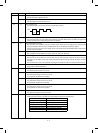
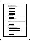
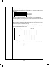
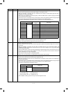
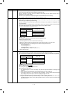
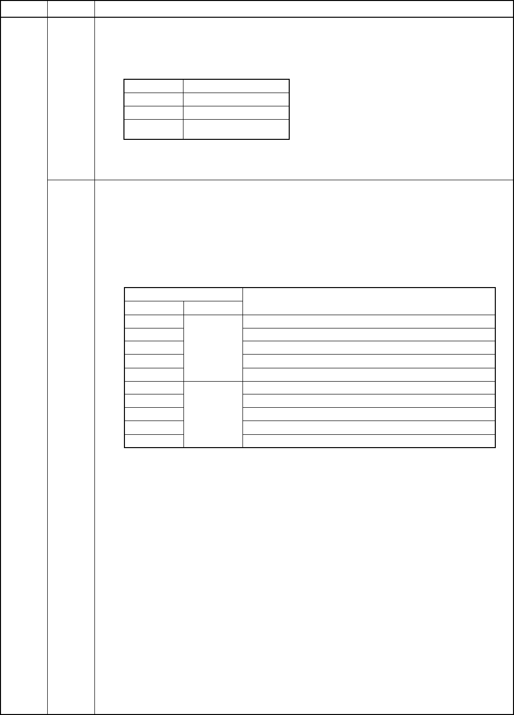
Display value Patch forming grid voltage
8 200 V Display range: 8 ∼ 99
When the display is
changed by 1, the
voltage is changed by 5V.
50 410 V
99 655 V
The drum surface data and the patch data after execution of this simulation can be checked with SIM 44-10.
(Note) When this simulation is executed, the patch forming grid voltage is stored, and the grid voltage amount may
be changed from the patch forming grid voltage before and after execution.
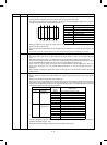
07 Image density sensor, drum mark sensor operation test
Used to read the light reception level for the light emitting amount of the image density sensor and the drum mark
sensor and to display on the copy quantity display.
When this simulation is executed, the light emitting levels of the image density sensor and the drum mark sensor
are changed in 5 steps and each light reception level is read.
After completion of operation, the measured data are displayed on the copy quantity display.
Since there are two or more display items, the third digit is used to make distinction between the light reception
level and the original judgment level, and the lower two digits are used to display the data.
The display is selected by the magnification ratio key.
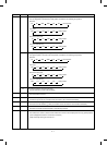
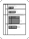
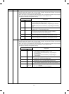
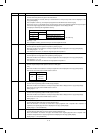
Copy quantity display
Display data
3rd digit 2nd, 1st digits
A Measured
data
Image density sensor input value, when light emitting 1V
b Image density sensor input value, when light emitting 2V
C Image density sensor input value, when light emitting 3V
d Image density sensor input value, when light emitting 4V
E Image density sensor input value, when light emitting 5V
F Judgement
data
Drum mark sensor level, when light emitting 1V
G Drum mark sensor level, when light emitting 2V
H Drum mark sensor level, when light emitting 3V
I Drum mark sensor level, when light emitting 4V
J Drum mark sensor level, when light emitting 5V
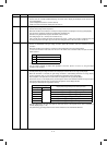
The data displayed with the lower two digits:
“A” ∼ “E”: Image density sensor A/D input value. Converted into a decimal number and displayed. (Display range:
0 ∼ 99)
“F” ∼ “J”: Drum mark sensor level is displayed with 0 and 1.
“0”: Drum mark sensor sensing impossible
“1”: Drum mark sensor sensing possible
8 – 14