


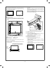
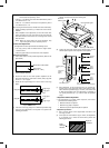
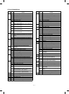
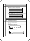

(11) Make a normal copy and check that the image loss and the
void amount are within the specified range.
(Specified range)
• Image loss: 0 ∼ 4mm
• Void amount: 1 ∼ 3mm
(12) Press the clear key and cancel simulation 50-01.
Note: When the RRC-A and RRC-B values are changed
in simulation 50-01, be sure to adjust the copy lead
edge void area.
When adjustment is made with simulation 50-02:
<Note> The keys and display functions are the same as simulation
50-01. In simulation 50-02, L1 and L2 values can be direct-
ly set. It is easy and simple. The void area adjustment is
also the same as simulation 50-01.
[Adjustment procedure]
(1) Put a scale on the original table.
(2) C → P → 0/◊ → P → 5 →
0/◊ → PSW → 2 → PSW
With the above key operation, simulation50-02 is performed
and the machine starts warming up.
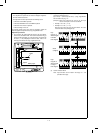
(3) The lower two digits of L1 value is displayed on the copy
quantity display. The top digit is for data identification.
• L1 : Lead edge shift at 200% (|||mm, 3 digits)
• L2 : Lead edge shift at 100% (✕✕✕mm, 3 digits)
Example of display
• For 42.5mm, the display is 2 5 .
(4) Use the % key and the 10 digit key pad to set A and b values
to zero. Make copies at 100% and 200%.
• 0/◊ → 0/◊ → 0/◊ → % key → 0/◊
→ 0/◊ → 0/◊ → PSW (A copy at 100% is made.)
• Enlargement key → (Lens shift, ready) → PSW (A copy
at 200% is made.)
(5) Measure the distance between the copy paper lead edge and
the copy image lead edge in each copy. Enter L1 and L2
values with the zoom key and the 10 digit key pad. With this
operation, RRC-A and RRC-B values in simulation 50-01 are
automatically calculated and stored.
Input procedure
(Example)
When L1 = 24.5 mm and L2 = 15.0mm:
Check that the lowest digit of the magnification ratio display is
"A," and perform the following key operation.
2 → 4 → 5 ("45" is displayed on the copy quantity display.)
→ % key → 1 → 5 → 0 ("50" is displayed.) → PSW
(6) After this, check shift and image loss, and void amount in each
copy similarly to simulation 50-01.
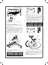
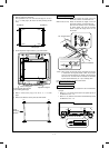
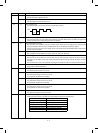
2-4. Original detecting section
A. Original detecting arm unit adjustment
1
OC switch ON timing adjustment
Execute simulation 40-01. (C → P → 0 → P → 4 → PSW → 1
→ PSW)
• Slowly tilt down the original detecting arm unit and loosen the
original cover switch actuator adjustment screw so that the
auto paper selection display lamp turns off when the height
from the table glass to the arm unit top is 36.5 ±0.5mm. Then
slide the actuator to adjust. (If the original cover ON timing is
shifted, the original detecting function may malfunction.)
10 20 30 40
50
Void area
0~3mm
Paper end
Scale image
Solid edge
Image loss
0~4mm
Full-size(100%) copy
36.5 0.5
Original detecting arm unit
Glass
Original cover switch actuator
Actuator
adjustment
screw
7 – 15