


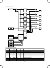
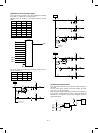
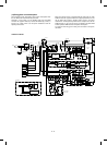
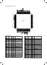

(9) AE (Auto Exposure) sensor circuit
The AE sensor circuit is composed of the AE sensor PWB; which is composed of the photo diode, the I-V convertor circuit, and the amplifier circuit;
and the amplifier circuit on the control PWB.
Operation amplifier A performs I-V conversion of the original density level (minute current) from the sensor. Operation amplifiers B and C amplify the
output of operation amplifier A to a suitable level for inputting to the CPU.
The amplifying level is automatically set by selecting the AE gain signal (AEG0 ∼ AEG2) outputted from the I/O chip when test command SIM 47 is
executed.
AE operation is performed by the software in the control PWB. When a reflected ray enters the sensor, a voltage corresponding to the light quantity
is inputted to the CPU. The CPU compares the input voltage and the copy lamp application voltage and controls the copy lamp voltage so that the
exposure level corresponds to the original density.
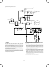
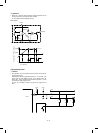
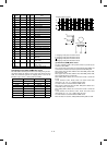
(10) Toner supply motor drive circuit
IC104 is the motor control IC which drives the toner supply motor with
the pulse signals (TMa, TMb) outputted from the I/O chip.
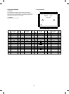
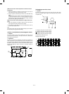
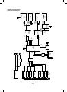
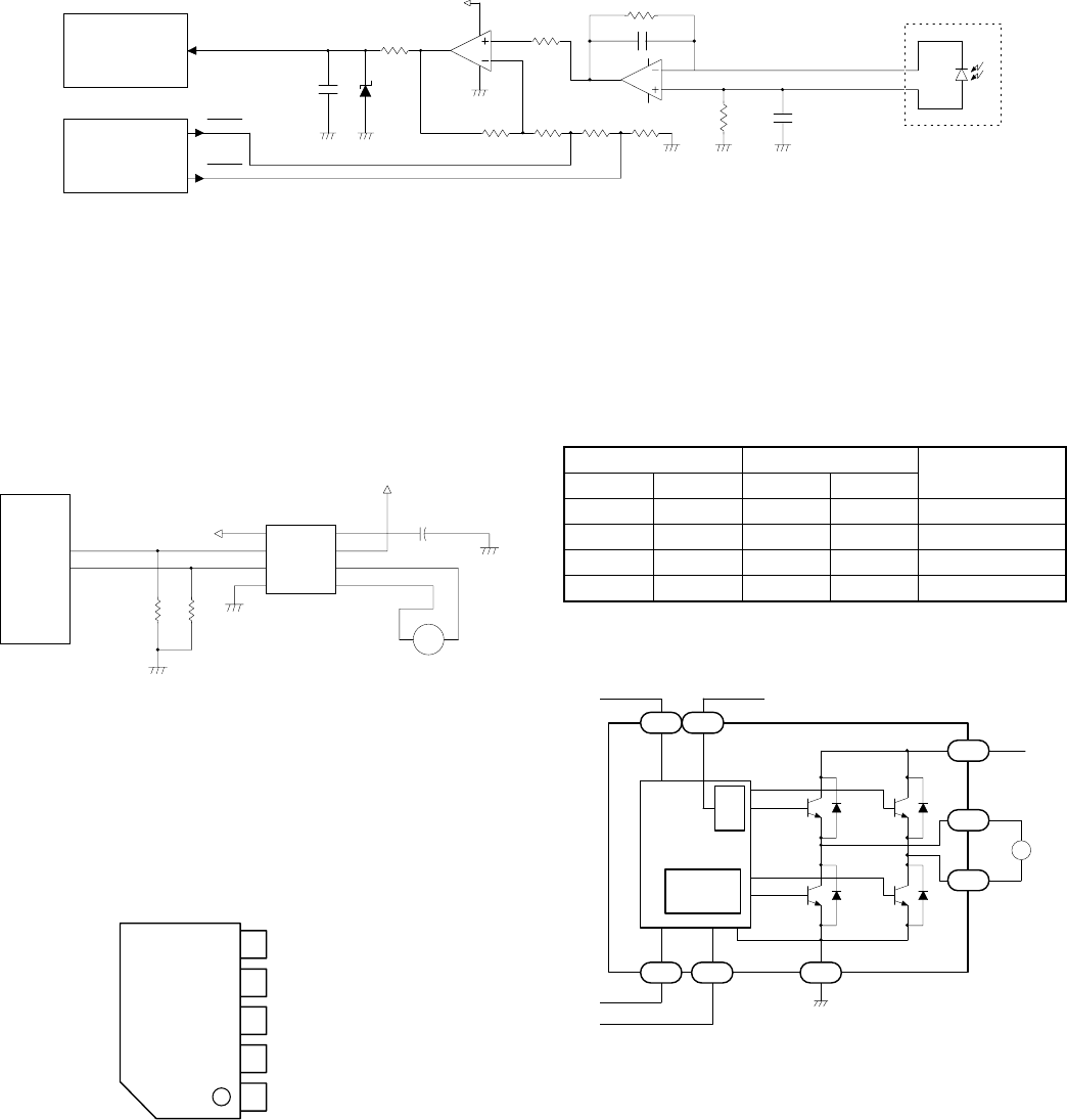
(11) Reset IC (IC13)
1 General
The M51953 BL is the semiconductor IC most suitable to detect the
power voltage and reset the logic circuit of every type including the
CPU.
It is provided with the built-in delay circuit. Delay time is easily ob-
tained by adding external capacity.
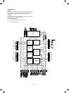
Pin connections (Top view)
Truth value table
Input Output
Mode
TMa TMb TMa TMb
LL∞∞ Stop
H L H L CW/CCW
L H L H CCW/CW
H H L L Break
∞: High impedance
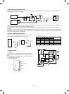
Internal circuit
11
AES
AEG1
AEG0
2
3
4
R53
1KJ
C38
1000PF
ZD2
HZS883
R40
1KJ
1
+24V
IC14A
LM324
R44
15KF
R43
750F
R45
75F
R47
270F
AEG1
AEG0
R50
100KJ
C48 0.1µ F
5
6
7
IC14B
LM324
R48
100KJ
C49
2200PF
PDK
PDA
AN0
CPU
I/O
AE sensor PWB
TMa
TMb
R20
47KJ
R211
47KJ
2
9
1
5
+5V
IC5
TA7291S
IN1
IN2
GND
6
8
7
3
M
+
C2
10UF35V
TMa
TMb
+24V
I/O
1
2
3
4
5
M51953 BL
External view 5P5
Power
NC
GND
Delay capacity
Output
2
8
9
1
5
6
7
3
M
REG
GND
Protection
circuit
(Heat insulated)
+5V
+24V
TMa
TMb
+24V
TMa
TMb
4
pin = NC pin
12 – 14