


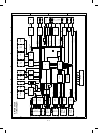

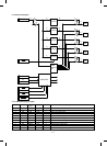
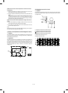
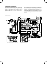
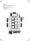
(4) Detector circuit of sensor signal
The LS151 selects one signal of D0 ∼ D7 according to the combina-
tion of SEL A ∼ C signals (H, L) and outputs it to Y.
Selection of D0 ∼ D7 for SEL A ∼ C is made as shown in the table
below.
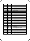
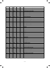
SEL C SEL B SEL A Y
0000
0011
0102
0113
1004
1015
1106
1117
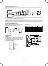
The sensor signal is in the following composition with the matrix of
SEL A ∼ C and S0 ∼ 2.
S0 S1 S2
SEL A PED1 — CSD 0
SEL B SW
A
⁄
B
POD CSD 1
SEL C PPD1 PNC CSD 2
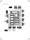
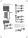
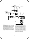
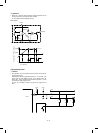
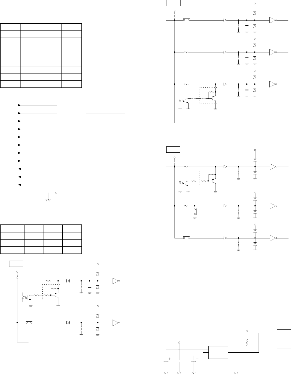
(5) Start/stop control circuit
This circuit detects ON/OFF of the power and controls start/stop of
the circuits.
The DC power section provides each power voltage (VH=+32V,
+24V, VC=+1-V, VD1=5V, VD2=5V).
When the power voltage reaches the specified level, the operation of
each circuit is started. Before the paper voltage falls below the
specified level, the operation of each circuit is stopped to prevent
against malfunctions.
D0
4
Y
CPU
5
D1
3
D2
2
D3
1
D4
15
D5
14
D6
13
D7
12
A
SEL A
11
B
SEL B
10
C
SEL C
9
IC15
G
7
74LS151
SEL A
I/O
+5V
1K
4.7K
10K
2.2K22K
24K
+5V
HC04
S0
DTA123YS
PE1
EE-SX1042
24K
+5V
HC04
S2
CSD0
SW601
MOTOR PWB 2 LS151
MOTOR PWB 3 LS151
SEL B
I/O
+5V
10K
2.2K
22K
24K
+5V
HC04
S2
DTA123YS
POD
GP1S53
24K
+5V
HC04
S0
CSD1
SW602
MAIN LS151
TMOTOR2 LS151
TMOTOR3 LS151
4.7K
24K
+5V
HC04
S1
4.7K
SEL C
I/O
+5V
10K
2.2K22K
24K
+5V
HC04
S0
DTA123YS
PPD1
GP1S53
24K
+5V
HC04
S1
4.7K
24K
+5V
HC04
S2
4.7K
1K
PNC
CSD
C5
470µ F
10V
C42
22000PF
1
2
4
VCC
NC
CAP
/RESET
GND
5
3
63
RESET
CPU
(IC 6)
R8
2.7KJ
C4
1µ F
10V
5V2
5V2
IC13
M51953BL
12 – 11