


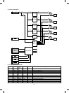
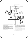
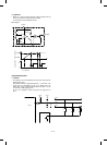
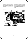
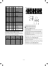


(13) EnergyStar circuit description
The EnergyStar circuit composition saves power consumption when
the user leaves the machine with the power ON.
Normally in a copy mode or in the standby mode, the main PWB
connector HL signal is HIGH (5V) and the AC PWB relay (TY201) is
turned on to supply power to all the power transformers and the
optional power source.
When the machine is left un-operated with the power ON, the main
PWB connector HL signal level becomes a high impedance to turn off
the AC PWV relay (RY201), stopping power supply to the power
transformers and the optional power source except for the sub DC
PWB PT2 (Ref. t1). As a result, only 5V is supplied to the main PWB
and the operation PWB to reduce the power consumption.
To reset from this energy save mode, press an button on the opera-
tion PWB.
OPTION
SORTER
DC PWB
GND
5V2
AC PWB
PR
HOUND AC CIRCUIT
AC IN
AC PWB
N/F
ILSW
LI
NI
LO
NO
L1
N1
OEG
OMH-SS-
105LM
AC PWB
PT1
VH
+24V
Vcl
+5V1
DC PWB
HV
VFMMirM
LMCFM
SFM
M A I N
P W B
TM
+5V1
MOTOR
MM
DSW
HOUND-B ONLY
ADF
CONTROL
ADF
DCPS
+24V
GND
+5V
JQ1-24V
(AJQ1342)
24V
JAPAN ONLY
AC
PWB
DHSW
SUB
DC
PWB
PT2
~
~
+
-
+
OPTION
MOTOR
ADF OPTION PWB
+28V
CONTROL
PWB
CS2M
CS3M
OPTION
CS4M
DC PWB
+5V1
MOTOR
PWB
DESK MOTOR DRIVE PWB
~
+-
POWER
DESK DC
OPTION
DH3
DH4
DH5
DH1
DH2
GATE
T1
GATE
T1
PT3
~
~
VH
+5V2
GND
D304
D301
OP PWB
ADUD
SF-2120/1120
only
ADU PWB
+5V
+24V
GND
+24V
VH
(MAIN,OP)
_
+
~
SUB DC PWB
CLR
T2
T2
AC PWB
200V
AREA
THSW
HL TRG
AC PWB
200V
AREA
DC
CIRCUIT
120V
L2
N1
200V ONLY
PT1
ADF DCPS
THSW
N2
CLTF
CLTF
HL:1kW
CL:100V 275W
200V 310W
“d ¹
XBb`
RY201
CONTROL
PWB
CONTROL
PWB
++
+
+
CL
CL
HL
HL
VH
12 – 16