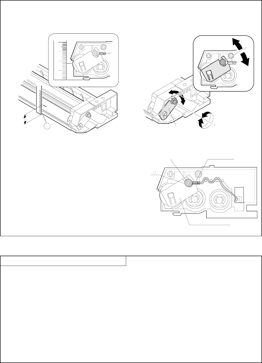
(5) Measure the distance from the marking position to the bottom
(A) of the developing unit and check that the distance is
17.6mm. If the distance is not as specified above, loosen the
MG adjustment plate fixing screw, move the adjustment plate
in the arrow directions and perform procedures (3) to (5) again.
(6) After completion of adjustment, tighten the MG adjustment
plate fixing screw. When tightening, check that the bias ter-
minal is as shown below. After tightening the screw, apply
screw lock to it.
A
17.6mm
MG adjustment plate
MG adjustment plate fixing screw
Bias terminal
MG adjustment plate
2. Optical system
2-1. Adjustment items
1. Lens reference position adjustment
2. No. 4/5 mirror reference position adjustment
3. Vertical copy magnification ratio adjustment
4. Resolution adjustment
5. Horizontal copy magnification ratio adjustment
6. Comparison table of lens values and simulation input values
7. Vertical skew adjustment
8. Horizontal skew adjustment
9. Center shift adjustment
10. Exposure balance adjustment
11. Copy lead edge adjustment
7 – 2


