


[6] DISASSEMBLY AND ASSEMBLY
The descriptions are divided into the following sections.
1. Paper feed section
2. Transport section and power section
3. Fusing section
4. Optical system
5. SPF section
6. Drum section
7. Developing section
8. Operation panel section and intermediate cabinet
9. Major parts on the frame side
10. Manual multi paper feed unit (SF-MF15, option)
11. Paper feed unit (SF-CM15, SF-CM16, option)
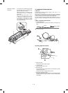
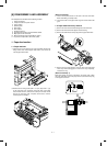
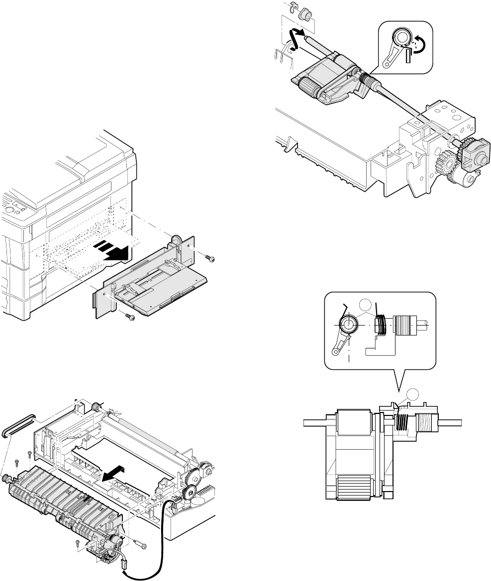
1. Paper feed section
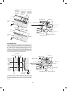
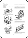
1-1. Paper feed unit
1 Open the front cover and lift up the upper clamshell. Remove two
fixing screws of the manual paper feed section, and remove the
manual paper feed section.
2 Remove the four fixing screws (M4 x 10 x 1pcs, step screw x 1 pc)
of the paper feed unit, and lift the rear frame side of the paper
feed unit and remove it. (Since there is the 8-pin connector on the
back of the rear frame side, it requires some force to remove.
Carefully pull it out straight.)
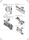
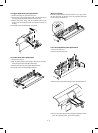
(Note for assembly)
1) There is the 8-pin connector on the back of the rear frame side.
When assembling it, carefully insert.
2) The belt must be on the paper feed unit gear and the resist roller
gear.
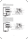
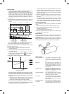
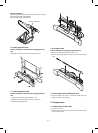
1-2. Paper feed roller ass’y removal
1) Remove the rear frame side electromagnetic clutch connector.
2) Remove the front frame side stopper and the bearing.
3) Remove the roller release arm spring from the paper feed frame.
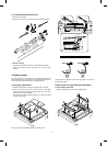
4) Remove the rear frame bearing, and one side of the paper feed
roller ass’y will be disengaged. To remove the ass’y completely,
remove the E-ring.
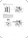
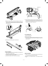
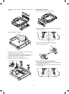
(Note for assembly 1)
With roller release arm spring A hooked on the spring notch, attach
the paper feed roller ass’y to the paper feed unit, and hook the spring
on the paper feed frame.
A
A
6 – 1