8. Set the mode.
Plug the copier into a grounded outlet and turn the power switch
on.
• Operate the keys on the copier to set the mode.
The above key operation will display the currently set mode.
• Immediately after the above key operation, operate the keys as
follows:
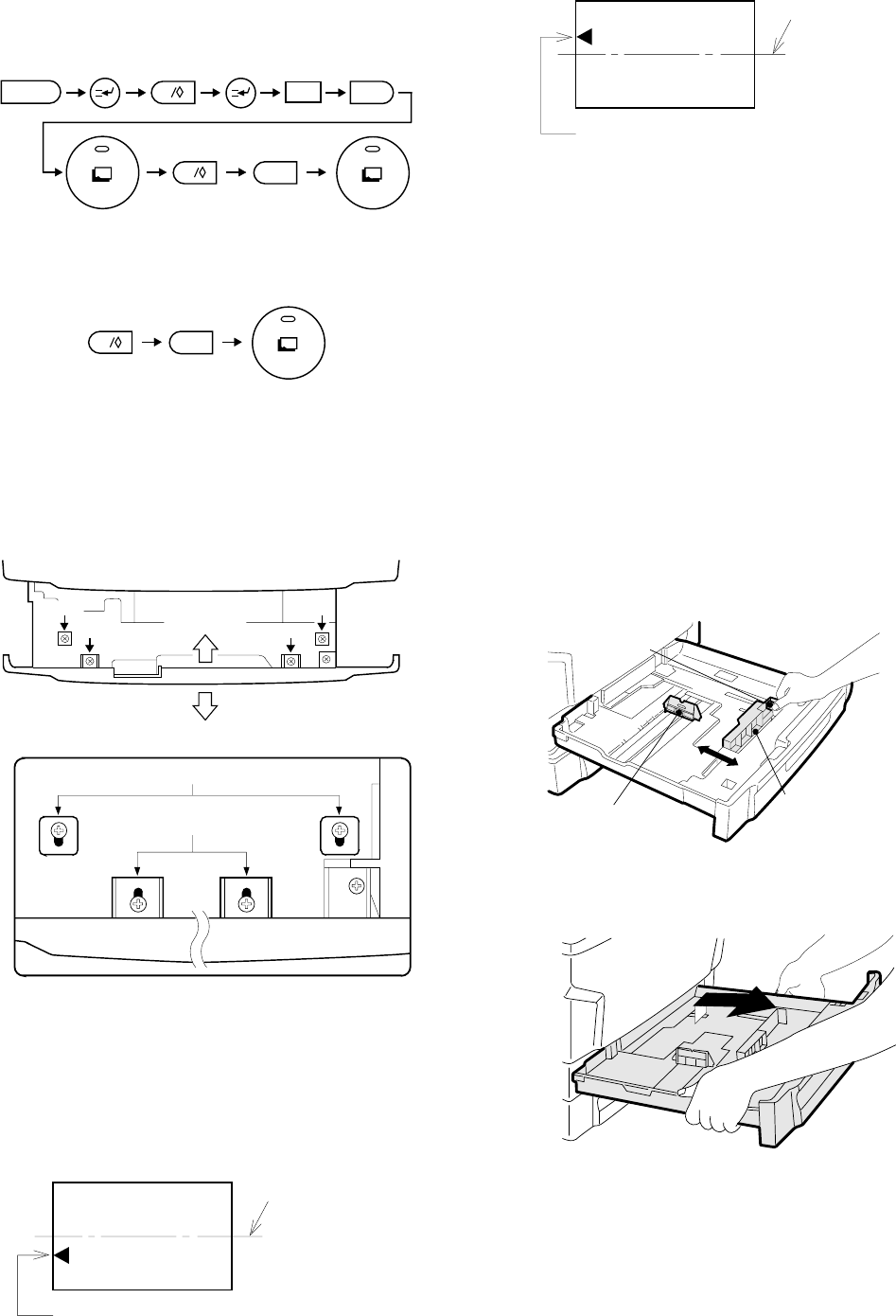
9. Centering the paper
The paper trays are adjusted at the factory, so there should be
no need to center the copy paper yourself. If such an adjustment
is necessary, however, follow the procedures described below.
Make a copy. If it comes out off center as shown in either figure 1 or
figure 2 below, loosen the four screws which hold the front part of the
tray in place.
[Note] When tightening down the front part of the tray, the two "b"
securing screws must be the same distance from the front
part of the tray. This requirement also applies to the two "a"
securing screws.
• When copies come out off center as shown in figure 1
Move the front part of the tray in direction A, tighten first the two
"a" securing screws then the two "b" securing screws, then make
another copy to check whether the copies come out properly
centered.
• When copies come out off center as shown in figure 2
Move the front part of the tray in direction B, tighten first the two
"a" securing screws then the two "b" securing screws, then make
another copy to check whether the copies come out properly
centered.
13. Tray paper size selection
(Described with the SF-1020)
Select the necessary size according to the following procedures.
(A5 size paper is treated as a special size. When shipping, the size is
set to A3.)
1. Fit the partition plates in the tray according to the
paper size (horizontal and vertical).
Be sure to fit with the paper scale position.
Partition plate A can be slid. Hold the fixing grip and slide it to the
proper paper size position.
Partition plate B is of insert-type. Remove it and insert to the suitable
paper size position.
2. Remove the tray.
Pull out the tray completely toward you and tilt upward and remove.
C
2 6
0
10
1
0
Direction "A"
b
a
a
b
Direction "B"
[Schematic illustration]
b
a
Center line of copy paper
Center of copy image (before adjustment)
Center line of copy paper
Center of copy image (before adjustment)
Fixing grip
Partition plate (B)
Partition plate (A)
4 – 11


