


Communications Teledyne API T703/T703U Calibrator Operation Manual
122
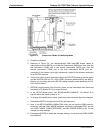
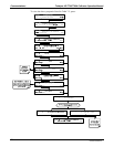
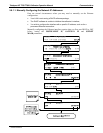
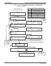
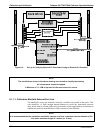
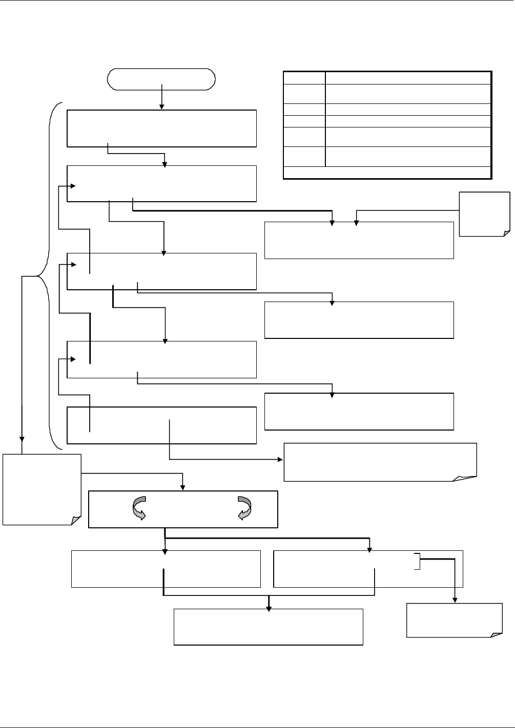
STEP 2: Configure the INSTRUMENT IP, GATEWAY IP and SUBNET MASK
addresses by pressing:
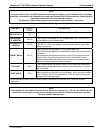
Internet Configuration Touchscreen Button Functions
BUTTON FUNCTION
[0]
Press to cycle through the range of numerals and
available characters (“0 – 9” & “ . ”)
<CH CH> Moves the cursor one character left or right.
DEL Deletes a character at the cursor location.
ENTR
Accepts the new setting and returns to the previous
menu.
EXIT
Ignores the new setting and returns to the previous
menu.
Some buttons only appear when applicable.
SETUP X.X DHCP: OFF
SET> EDIT EXIT
SETUP X.X INST IP: 000.000.000.000
<SET SET> EDIT EXIT
SETUP X.X GATEWAY IP: 000.000.000.000
<SET SET> EDIT EXIT
SETUP X.X INST IP: [0] 00.000.000
<CH CH> DEL [0] ENTR EXIT
SETUP X.X SUBNET MASK:255.255.255.0
<SET SET> EDIT EXIT
SETUP X.X SUBNET MASK:[2]55.255.255.0
<CH CH> DEL [?] ENTR EXIT
SETUP X.X TCP PORT 3000
<SET EDIT EXIT
The PORT number needs to remain at 3000.
Do not change this setting unless instructed to by
Teledyne Instruments Customer Service personnel.
From Step 1 above)
SETUP X.X GATEWAY IP: [0] 00.000.000
<CH CH> DEL [?] ENTR EXIT
Cursor
location is
indicated by
brackets
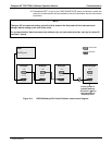
SETUP X.X INITIALIZING INET 0%
…
INITIALIZING INET 100%
SETUP X.X INITIALIZATI
O
N SUCCEEDED
SETUP X.X INITIALIZATION FAILED
SETUP X.X
COMMUNICATIONS MENU
ID INET COM1 EXIT
Pressing EXIT from
any of the above
display menus
causes the Ethernet
to reinitialize its
internal interface
firmware
Contact your IT
Network Administrator
07223C DCN6572