Principles of Operation Teledyne API T703/T703U Calibrator Operation Manual
198
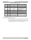
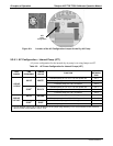
Table 9-1: Relay Board Status LEDs
LED COLOR DESCRIPTION FUNCTION/INDICATION
D1 Red
Watchdog Circuit; I
2
C bus
operation.
Blinks when I
2
C bus is operating properly
D2 Yellow Zero Air Pump (option) Status When lit the zero air AC pump is running.
D3-6
SPARE
D7 Green
Photometer Meas/Ref Valve
Status
When lit the valve open to the Measure
gas path; when not lit while instrument is
running, the valve is open to the
Reference gas path.
D8
Green Zero Air Shutoff Valve (option) Status When lit, ZA shutoff valve open.
D9 Green O
3
Pump Status When lit, O
3
pump running
D10 Green T703U Divert Valve Status when lit, divert valve open.
D11 Green T703U O
3
Generator Valve Status When lit, O
3
generator valve open.
D12 - 14 SPARE
D15 Green Photometer Lamp Heater Status
When lit the photometer UV lamp heater
is on
D16 Green O
3
Generator Lamp Heater
When lit the O
3
generator UV lamp heater
is on
9.2.3.4. Relay PCA Watchdog Indicator (D1)
The most important of the status LEDs on the relay board is the red I
2
C Bus watchdog
LED. It is controlled directly by the calibrator’s CPU over the I
2
C bus. Special circuitry
on the relay PCA watches the status of D1. Should this LED ever stay ON or OFF for
30 seconds (indicating that the CPU or I
2
C bus has stopped functioning) this Watchdog
Circuit automatically shuts all valves and turns off all heaters and lamps.
07223C DCN6572


