


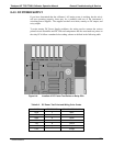
Teledyne API T703/T703U Calibrator Operation Manual General Troubleshooting & Service
181
8.4.9.5. Control Outputs
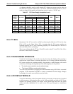
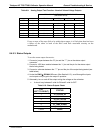
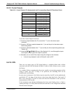
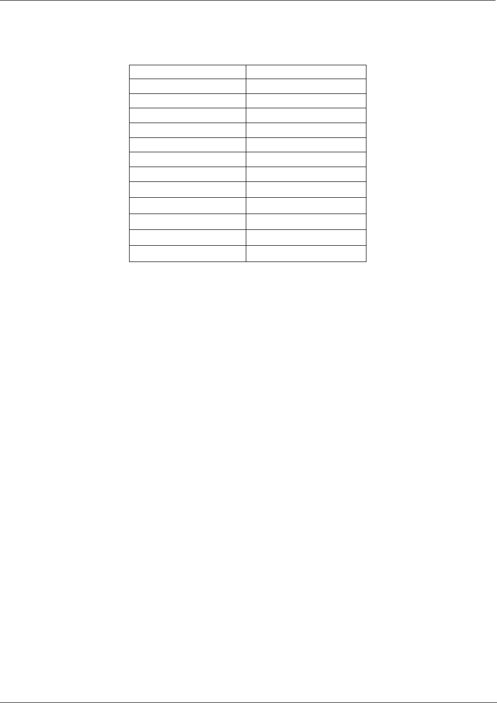
Table 8-12: Control Outputs Pin Assignments and Corresponding Signal I/O Functions Check
PIN (LEFT TO RIGHT) STATUS
1
CONTROL_OUT_1
2
CONTROL_OUT_2
3
CONTROL_OUT_3
4
CONTROL_OUT_4
5
CONTROL_OUT_5
6
CONTROL_OUT_6
7
CONTROL_OUT_7
8
CONTROL_OUT_8
9
CONTROL_OUT_9
10
CONTROL_OUT_10
11
CONTROL_OUT_11
12
CONTROL_OUT_12
To test the Control Output electronics:
1. Connect a jumper between the “E“ pin and the “” pin on the status output
connector.
2. Connect a 1000 ohm resistor between the “+” pin and the pin for the status output
that is being tested.
3. Connect a voltmeter between the “” pin and the pin of the output being tested (see
Table 8-12).
4. Under
the DIAG SIGNAL I/O menu (See Section8.1.3), scroll through the inputs
and outp
u
ts until you get to the output in question.
5. Alternately, turn on and off the output noting the voltage on the voltmeter.
It should vary between 0 volts for ON and 5 volts for OFF.
8.4.10. CPU
There are two major types of CPU board failures, a complete failure and a failure
associated with the Disk On Module (DOM). If either of these failures occurs, contact
the factory.
For complete failures, assuming that the power supplies are operating properly and the
wiring is intact, the CPU is faulty if on power-on, the watchdog LED on the
motherboard is not flashing.
In some rare circumstances, this failure may be caused by a bad IC on the motherboard,
specifically U57, the large, 44 pin device on the lower right hand side of the board. If
this is true, removing U57 from its socket will allow the instrument to start up but the
measurements will be invalid.
If the instrument stops during initialization (the front panel display shows a fault or
warning message), it is likely that the DOM, the firmware or the configuration and data
files have been corrupted.
07223C DCN6572