


Teledyne API T703/T703U Calibrator Operation Manual General Troubleshooting & Service
179
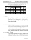
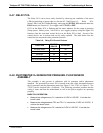
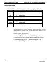
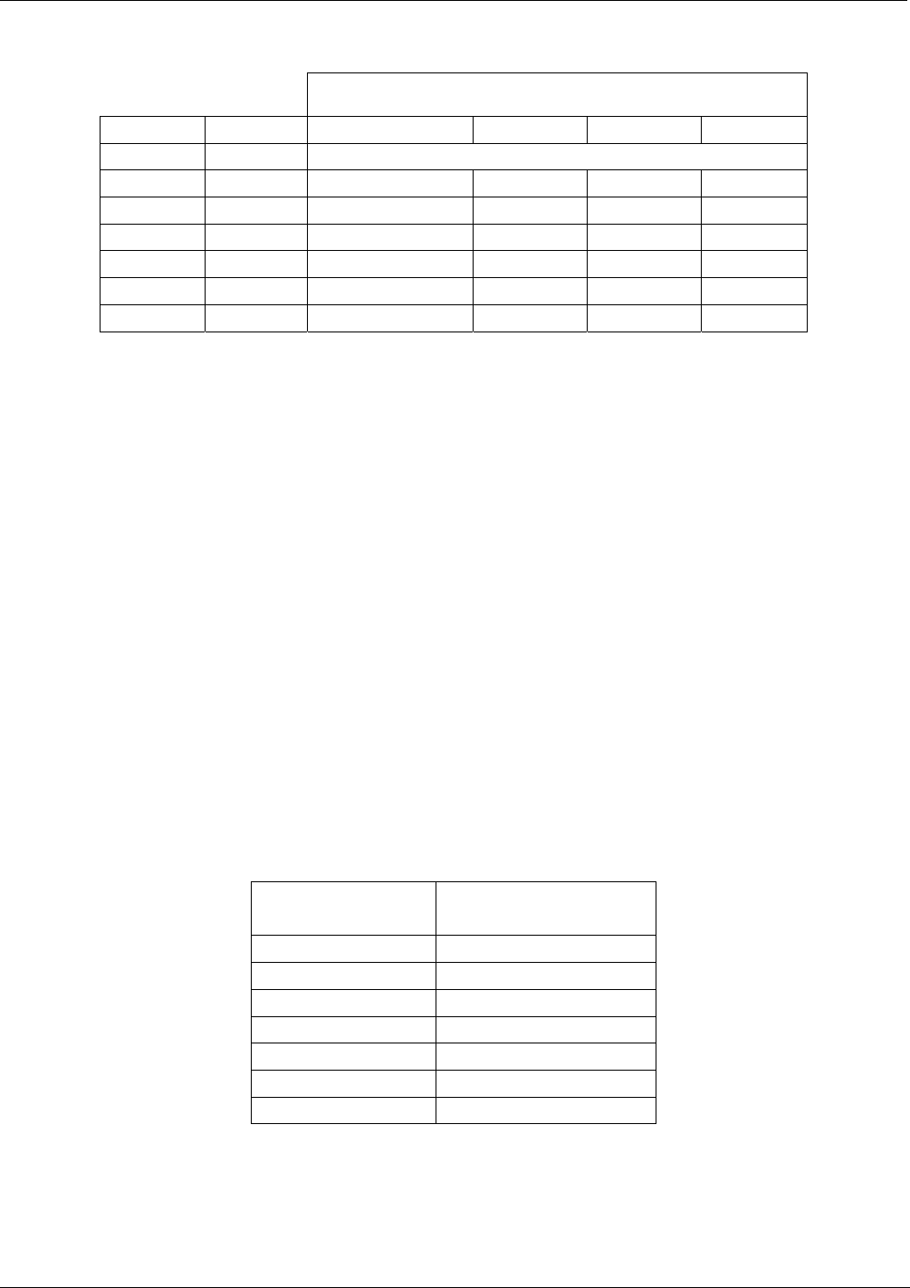
Table 8-9: Analog Output Test Function - Nominal Values Voltage Outputs
FULL SCALE OUTPUT OF VOLTAGE RANGE
(see Section 4.9.1.3)
100mV 1V 5V 10V
STEP % NOMINAL OUTPUT VOLTAGE
1 0 0 0 0 0
2 20 20 mV 0.2 1 2
3 40 40 mV 0.4 2 4
4 60 60 mV 0.6 3 6
5 80 80 mV 0.8 4 8
6 100 100 mV 1.0 5 10
If one or more of the steps fails to be within these ranges, it is likely that there has been
a failure of the either or both of the DACs and their associated circuitry on the
motherboard.
8.4.9.3. Status Outputs
To test the status output electronics:
1. Connect a jumper between the “D“ pin and the “” pin on the status output
connector.
2. Connect a 1000 ohm resistor between the “+” pin and the pin for the status output
that is being tested.
3. Connect a voltmeter between the “” pin and the pin of the output being tested (see
table below).
4. Under the DIAG SIGNAL I/O menu (See Section8.1.3), scroll through the inputs
and outp
u
ts until you get to the output in question.
5. Alternately, turn on and off the output noting the voltage on the voltmeter.
It should vary between 0 volts for ON and 5 volts for OFF.
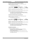
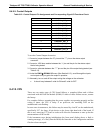
Table 8-10: Status Outputs Check
PIN
(LEFT TO RIGHT)
STATUS
1
ST_SYSTEM_OK
2
SPARE
3
ST_CAL_ACTIVE
4
ST_DIAG_MODE
5
ST_TEMP_ALARM
6
ST_PRESS_ALARM
7 and 8
SPARE
07223C DCN6572