


Teledyne API T703/T703U Calibrator Operation Manual Principles of Operation
193
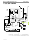
9.2. ELECTRONIC OPERATION
9.2.1. OVERVIEW
Photometer
Lamp Power
Supply
Photometer
Detector
Preamp
Absorption tube
Photometer
Detector
O
3
Generator
Analog Outputs
Aout 1
Aout 4
Analog Outputs
(D/A)
External Digital I/O
Power Up
Circuit
Sensor Inputs
PC 104
CPU Card
Disk on
Module
Flash
Chip
Aout 3
Aout 2
TEST
CHANNEL
OUTPUT
Status Outputs
1 - 8
Control Outputs
1 - 12
Control Inputs
1 - 12
O
3
Generator
Reference
Detector
I
2
C Bus
O
3
Generator
Lamp Supply
Thermistor Interface
Box
Temperature
Photometer Sample Gas
Pressure Sensor
O
3
Generator Input
Pressure Sensor
UV
Lamp
A/D
Converter
RELAY
PCA
Photometer
UV Lamp
Temperature
O3 Generator
UV Lamp
Temperature
Photometer Sample Gas
Temperature
FemaleMale
Dis
p
la
y
(RS-232 only)
(RS-232 or RS-485)
USB
Touchscreen
Photometer
Pump
Photometer
Lamp Heater
O
3
Generator
Lamp Heater
In T703U only.
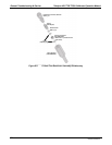
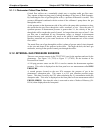
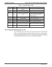
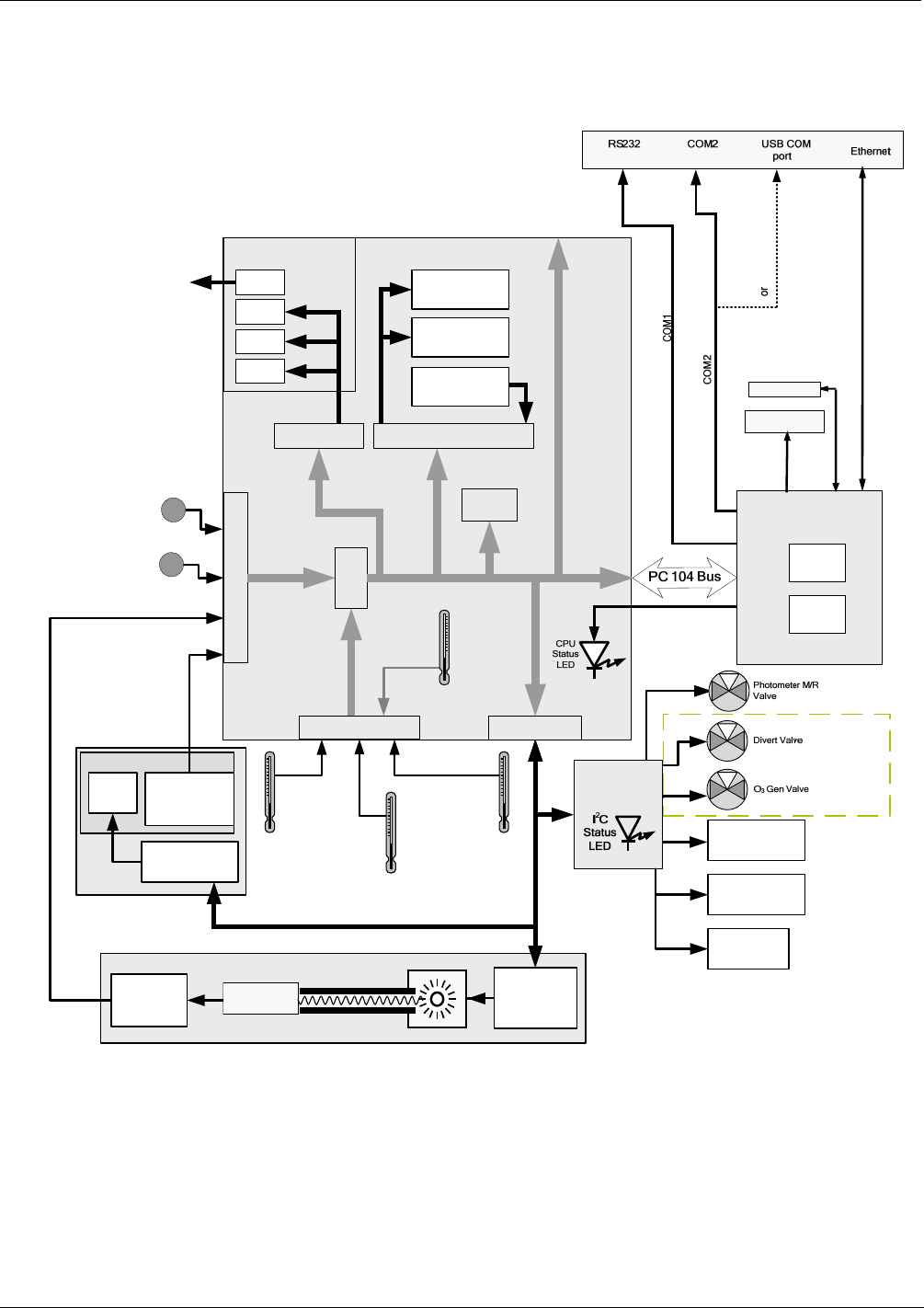
Figure 9-3: Electronic Block Diagram
The core of the calibrator is a microcomputer (referred to as the CPU) that controls
various internal processes, interprets data, makes calculations, and reports results using
specialized firmware developed by Teledyne API. It communicates with the user as
well as receives data from and issues commands to a variety of peripheral devices via a
separate printed circuit assembly called the motherboard.
07223C DCN6572