


Teledyne API T703/T703U Calibrator Operation Manual Principles of Operation
197
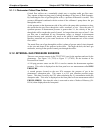
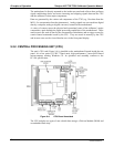
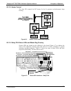
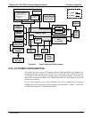
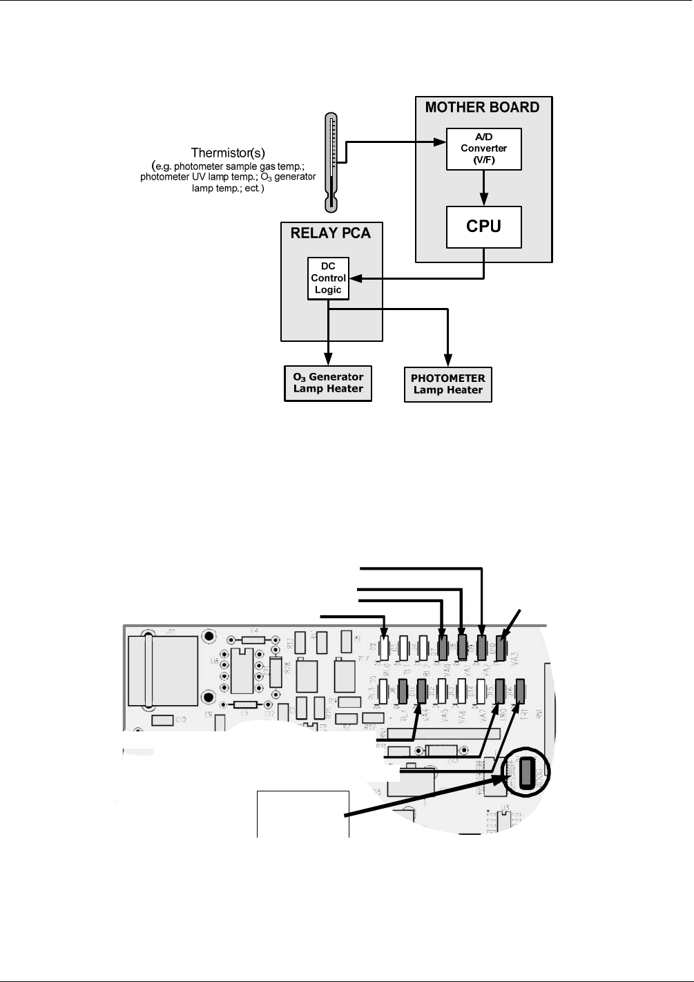
9.2.3.2. Heater Control
The relay PCA controls the DC heaters for the O
3
generator and photometer lamp
housing.
Figure 9-6: Heater Control Loop Block Diagram.
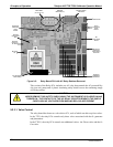
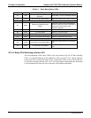
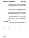
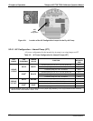
9.2.3.3. Relay PCA Status LEDs and Watch Dog Circuitry
Sixteen LEDs are located on the calibrator’s relay board (Figure 9-7) to indicate the
status of the calibrator’s heating zones and some of its valves; included is a general
operating watchdog indicator. Table 9-1 shows the states of these LEDs and their
respective functionality
. Not all LEDs are used.
D15 (Green) - Photometer Lamp Heater
D16 (Green) – O
3
Generator Lamp Heater
D7 (Green) – Photometer Meas/Ref Valve
D9 (Green) – O
3
Pump
D1 (RED)
Watchdog
Indicator
T703U only:
D10 (Green)
O
3
Divert Valve
T703U only: D11 (Green) – O
3
Generator Valve
D2
(
Yellow
)
–
Zero Air Pum
p
O
p
tion
D8 (Green) – Zero Air Shutoff Valve Option
Figure 9-7: Status LED Locations – Relay PCA
07223C DCN6572