


Getting Started Teledyne API T703/T703U Calibrator Operation Manual
24
Remove the 2 screws fastening the top cover to the unit (one per side towards
the rear).
Slide the cover backwards until it clears the calibrator’s front bezel.
Lift the cover straight up.
4. Inspect the interior of the instrument to make sure all circuit boards and other
components are in good shape and properly seated.
5. Check the connectors of the various internal wiring harnesses and pneumatic hoses
to make sure they are firmly and properly seated.
6. Verify that all of the optional hardware ordered with the unit has been installed.
These are checked on the paperwork accompanying the calibrator.
VENTILATION CLEARANCE: Whether the calibrator is set up on a bench or
installed into an instrument rack, be sure to leave sufficient ventilation clearance.
AREA MINIMUM REQUIRED CLEARANCE
Back of the instrument 10 cm / 4 inches
Sides of the instrument 2.5 cm / 1 inch
Above and below the instrument. 2.5 cm / 1 inch
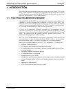
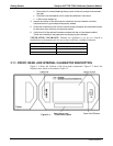
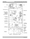
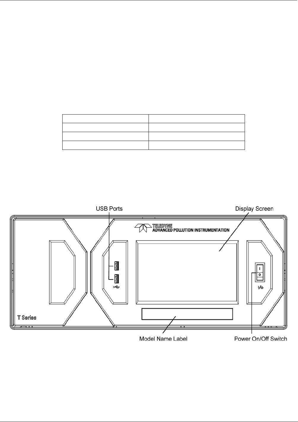
3.1.1. FRONT, REAR, AND INTERNAL CALIBRATOR DESCRIPTION
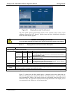
Figure 3-1 shows the location of the front panel components. Figure 3-2 shows the
display screen, which is described in Table 3-1.
Figure 3-1: Front Panel Layout
07223C DCN6572