


Operating the Calibrator Teledyne API T703/T703U Calibrator Operation Manual
60
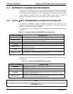
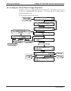
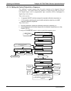
4.5.1.6. Setting Up Control Outputs for a Sequence
The calibrator’s control outputs allow the entire sequence to be triggered from an
external source. This feature allows the calibrator to control devices that accept logic-
level digital inputs, such as programmable logic controllers (PLCs), dataloggers, or
digital relays/valve drivers.
They can be used as:
12 separate ON/OFF switches assigned to separate calibration sequences, or;
A 12-bit wide bus allowing the user to define activation codes for up to 4095
separate calibration sequences.
They can be set to:
Be active whenever a particular calibration sequence is operating, or;
Activate/deactivate as individual steps within a calibration sequence are run See
Section 4.5.2.5).
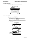
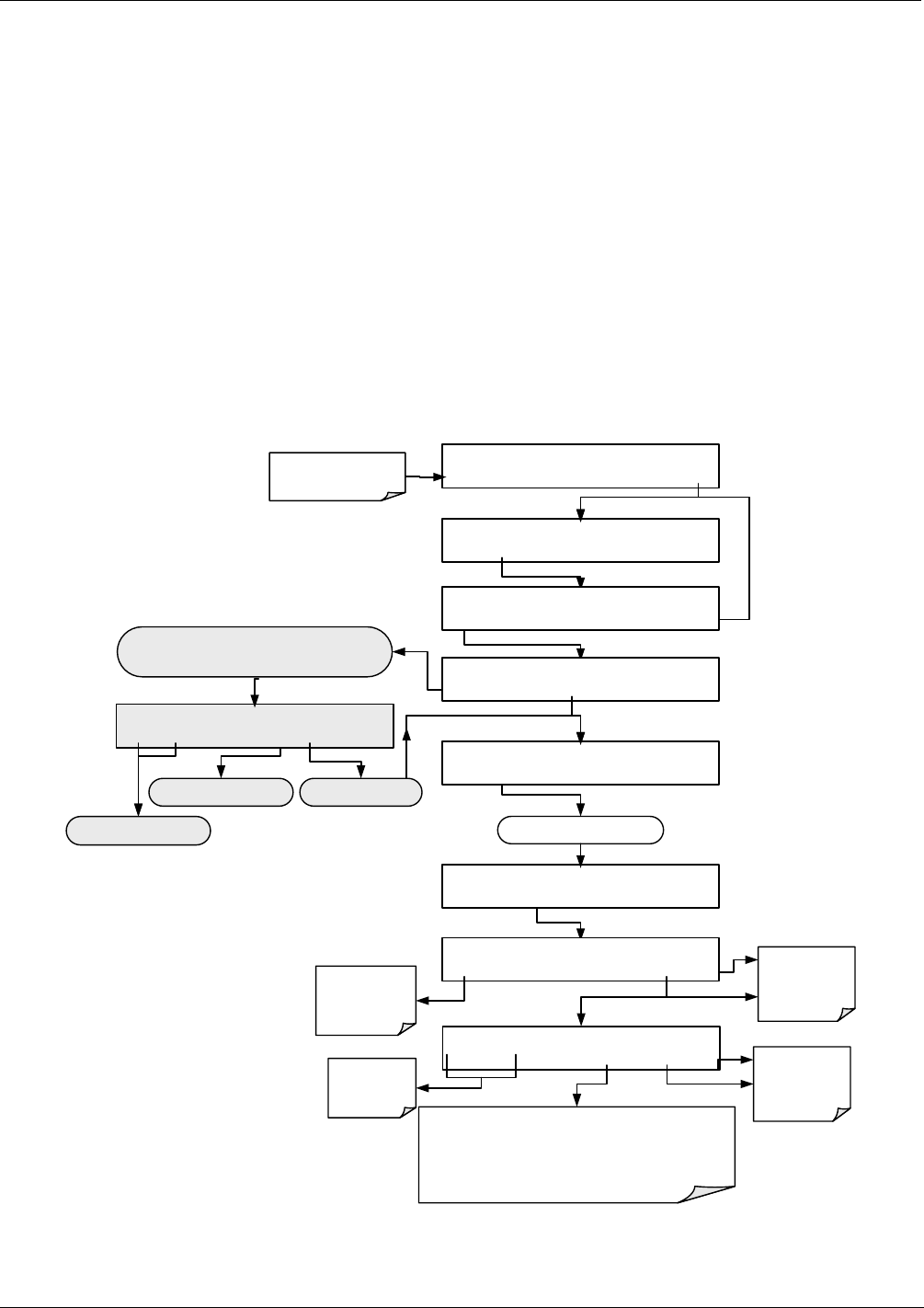
To assign a CC OUTPUT pattern / code to a particular sequence, press.
STANDBY ACT =STANDBY
<TST TST> GEN STBY SEQ SETUP
Make sure that the
calibrator is in standby
mode.
SETUP X.X PRIMARY SETUP MENU
O3 SEQ CFG CLK PASS MORE EXIT
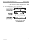
SETUP X.X SEQUENCE CONFIGURATION
EDIT PRINT EXIT
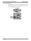
SETUP X.X END OF SEQUENCES
INS PRNT EXIT
SETUP X.X 1) SEQ [NAME], [X] STEPS
PREV NEXT INS DEL EDIT PRNT EXIT
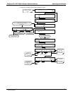
SETUP X.X NAME:0
SET> EDIT EXIT
Deletes the sequence shown
in the message field
Edits the sequence shown
in the message field
Scrolls back and forth between
existing sequences
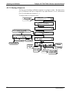
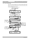
SETUP X.X CC OUTPUT:DISABLED
<SET SET> EDIT EXIT
Continue pressing SET> until ...
This display only appears if there are no sequences currently
programmed into the
calibrator.
OTHERWISE ...
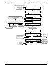
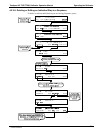
SETUP X.X CC OUTPUT:[0]00000000000
<CH CH> [0] ENTER EXIT
EXIT discards the
new setting
ENTR accepts the
new setting
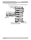
SETUP X.X CC OUTPUT ENABLE:OFF
OFF ENTER EXIT
Toggle to turn
the CC output
ON/OFF
EXIT discards the
new setting
ENTR accepts the
new setting
Toggle to turn the selected bit ON/OFF (0 or 1).
Each bit shown on the display represents one of the control
output pins located on the calibrator rear panel (see Figure 3-2),
The left most bit is Bit 1, the next bit to the right, bit 2,
progressing rightward to bit 12 (see Figure 3-10 for connector pin
assignments)
Moves the
cursor one
character left or
right.
07223C DCN6572