


Principles of Operation Teledyne API T703/T703U Calibrator Operation Manual
204
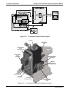
The LCD display is controlled directly by the CPU board. The touchscreen is interfaced
to the CPU by means of a touchscreen controller that connects to the CPU via the
internal USB bus and emulates a computer mouse.
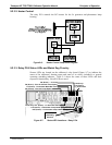
9.3.1.1. Front Panel Interface PCA
The front panel interface PCA controls the various functions of the display and
touchscreen. For driving the display it provides connection between the CPU video
controller and the LCD display module. This PCA also contains:
power supply circuitry for the LCD display module
a USB hub that is used for communications with the touchscreen controller and the
two front panel USB device ports
he circuitry for powering the display backlight
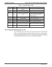
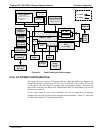
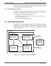
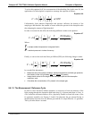
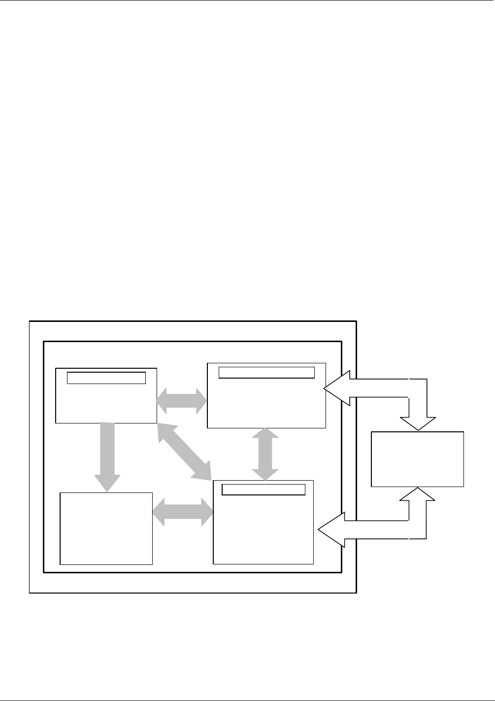
9.4. SOFTWARE OPERATION
The calibrator’s core module is a high performance, Vortex 86SX-based microcomputer
running Windows CE. Inside Windows CE, special software developed by Teledyne
API interprets user commands from the various interfaces, performs procedures and
tasks, stores data in the CPU’s various memory devices, and calculates the concentration
of the gas being sampled.
Windows CE
API FIRMWARE
Calibrator Operations
Calibration Procedures
Configuration Procedures
Autonomic Systems
Diagnostic Routines
Memory Handling
Calibration Data
System Status Data
Interface Handling
Sensor input Data
Touchscreen
Analog Output Data
RS232 & RS485
External Digital I/O
Measurement
Algorithms for
photometer
CALIBRATOR
HARDWARE
PC/104 BUS
PC/104 BUS
Figure 9-12: Schematic of Basic Software Operation
07223C DCN6572