


Maintenance Schedule & Procedures Teledyne API T703/T703U Calibrator Operation Manual
156
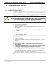
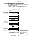
7.5. PHOTOMETER UV SOURCE LAMP ADJUSTMENT
This procedure details the steps for adjustment of the UV source lamp in the optical
bench assembly. This procedure should be done whenever the PHOTO REFERENCE
test function value drops below 3000 mV.
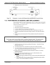
1. Make sure the instrument is warmed-up and has been running for at least 15
minutes before proceeding.
2. Remove the cover from the instrument.
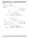
3. Locate the Photometer (see Figure 3-5)
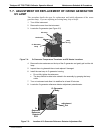
4. Locate
the UV DETECTOR GAI
N ADJUST POT on the photometer assembly (see
Figure 7-3).
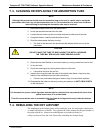
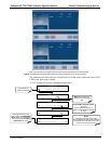
5. Perform the f
ollowing procedure:
Additional adjustment can be made by physically
rotating the lamp in it’s housing.
To do this, slightly loosen the UV lamp
setscrew.
Next, slowly rotate the lamp up to ¼ turn in
either direction while watching the
PHOTO_DET signal.
Once the optimum lamp position is
determined, re-tighten the lamp
setscrew
Using an insulated pot adjustment tool, Turn the UV
DETECTOR GAIN ADJUSTMENT POT until the value of
PHOTO_DET is as close as possible to 4600.0 MV.
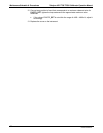
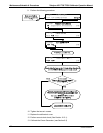
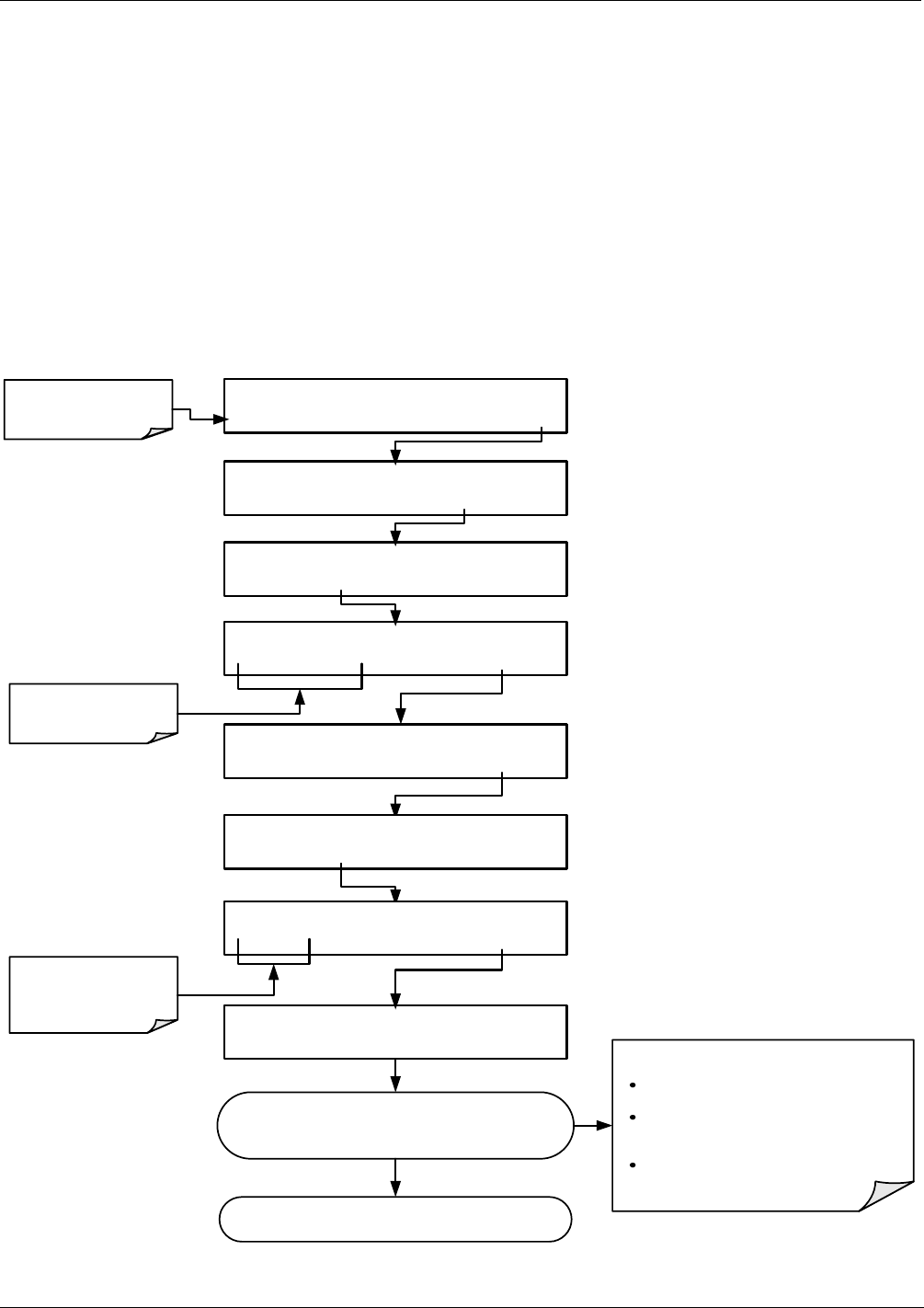
STANDBY ACT =STANDBY
<TST TST> GEN STBY SEQ SETUP
Make sure that the
instrument is in Standby
mode.
SETUP X.X PRIMARY SETUP MENU
O3 SEQ CFG CLK PASS MORE EXIT
SETUP X.X SECONDARY SETUP MENU
COMM VARS DIAG EXIT
SETUP X.X ENTER PASSWORD
818 ENTREXIT
Toggle these buttons to
enter the correct
PASSWORD
DIAG SIGNAL I/O
PREV NEXT ENTR EXIT
DIAG I/O 1) CONTROL_IN_2=OFF
PREV NEXT JUMP PRNT EXIT
DIAG 17) PHOTO_DET = 3342.2 MV
PREV NEXT PRNT EXIT
DIAG I/O JUMP TO:1
17 ENTREXIT
Toggle these buttons to
show the ID number for
the desired signal
(see Appendix A)
If a minimum reading of 3500.0 mV can not be reached,
the lamp must be replaced.
07223C DCN6572