


Principles of Operation Teledyne API T703/T703U Calibrator Operation Manual
194
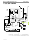
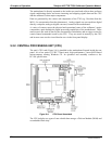
The motherboard is directly mounted to the inside rear panel and collects data, performs
signal conditioning duties and routes incoming and outgoing signals between the CPU
and the calibrator’s other major components.
Data are generated by the various sub components of the T703 (e.g. flow data from the
MFCs, O
3
concentration from the photometer). Analog signals are converted into digital
data by a unipolar, analog-to-digital converter, located on the motherboard.
A variety of sensors report the physical and operational status of the calibrator’s major
components, again through the signal processing capabilities of the motherboard. These
status reports are used as data for the concentration calculations and as trigger events for
certain control commands issued by the CPU. They are stored in memory by the CPU
and in most cases can be viewed but the user via the front panel display.
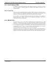
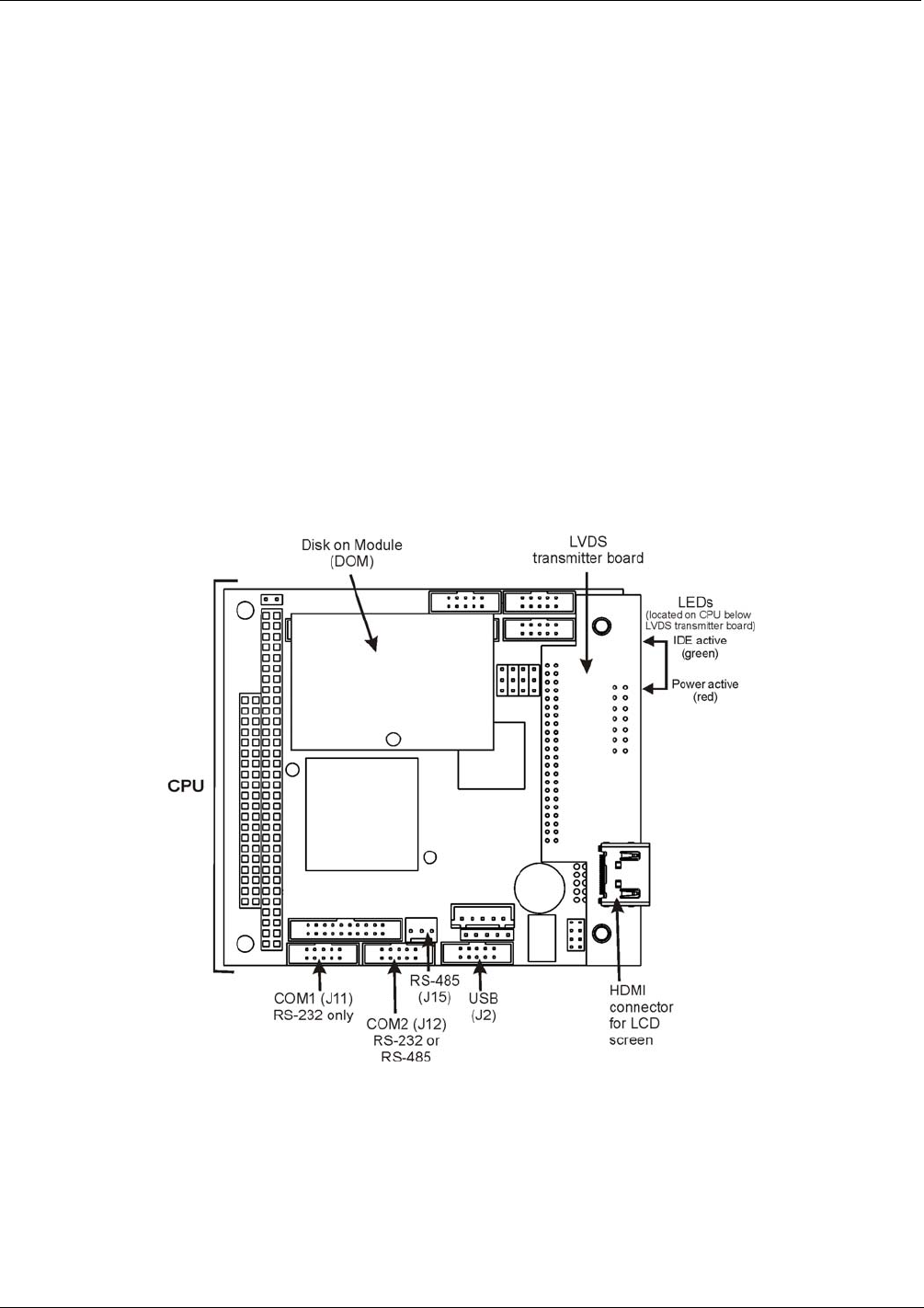
9.2.2. CENTRAL PROCESSING UNIT (CPU)
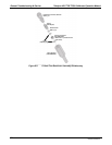
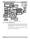
The unit’s CPU card (Figure 9-4) is installed on the motherboard located inside the rear
panel. It is a low power (5 VDC, 720mA max), high performance, Vortex 86SX-based
microcomputer running Windows CE. Its operation and assembly conform to the
PC-104 specification.
Figure 9-4: CPU Board Annotated
The CPU includes two types of non-volatile data storage: a Disk on Module (DOM) and
an embedded flash chip.
07223C DCN6572