


Getting Started Teledyne API T703/T703U Calibrator Operation Manual
34
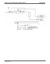
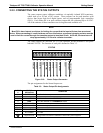
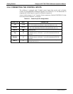
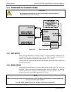
3.2.4. CONNECTING THE CONTROL INPUTS
The calibrator is equipped with 12 digital control inputs that can be used to Initiate
various user programmable calibration sequences (see Section 4.5.1.5 for instructions on
assigning the control inputs
to specific calibration sequences).
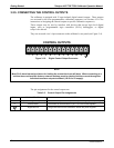
Access to these inputs is via 2 separate 10-pin connectors, labeled CONTROL IN, that
are located on the calibrator’s rear panel.
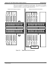
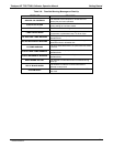
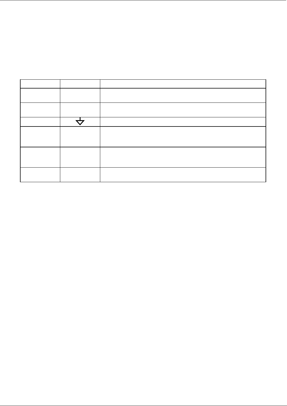
Table 3-4: Control Input Pin Assignments
CONNECTOR INPUT DESCRIPTION
Top 1 to 6
Can be used as either 6 separate on/off switches or as bits 1 through
6 of a 12 bit wide binary activation code (see Section 4.5.1.5)
Bottom 7 to 12
Can be used as either 6 separate on/off switches or as bits 7 through
12 of a 12 bit wide binary activation code (see Section 4.5.1.5)
BOTH
Chassis ground.
Top U
Input pin for +5 VDC required to activate pins A – F. This can be from
an external source or from the “+” pin of the instruments STATUS
connector.
Bottom U
Input pin for +5 VDC required to activate pins G – L. This can be from
an external source or from the “+” pin of the instruments STATUS
connector.
BOTH
+
Internal source of +5V that can be used to actuate control inputs when
connected to the U pin.
07223C DCN6572