


Calibration and Verification Teledyne API T703/T703U Calibrator Operation Manual
142
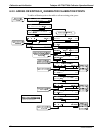
The calculated photometer sample gas flow value is viewable on the instrument’s front
panel using the PHOTO FLOW test function and can be output via the TEST
CHANNEL output using the SAMPLE FLOW function.
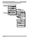
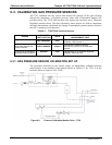
CALCULATING THE OUTPUT GAS FLOW RATE
This flow rate is calculated by applying a separate slope factor, also stored in the
calibrator’s memory, to an interpolated valued based on the following table of internal
gas pressure as measured by the O
3
gas input pressure sensor. The output-flow slope
value is determined by performing an OUPUT FLOW calibration operation (see
Section 6.4.2).
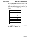
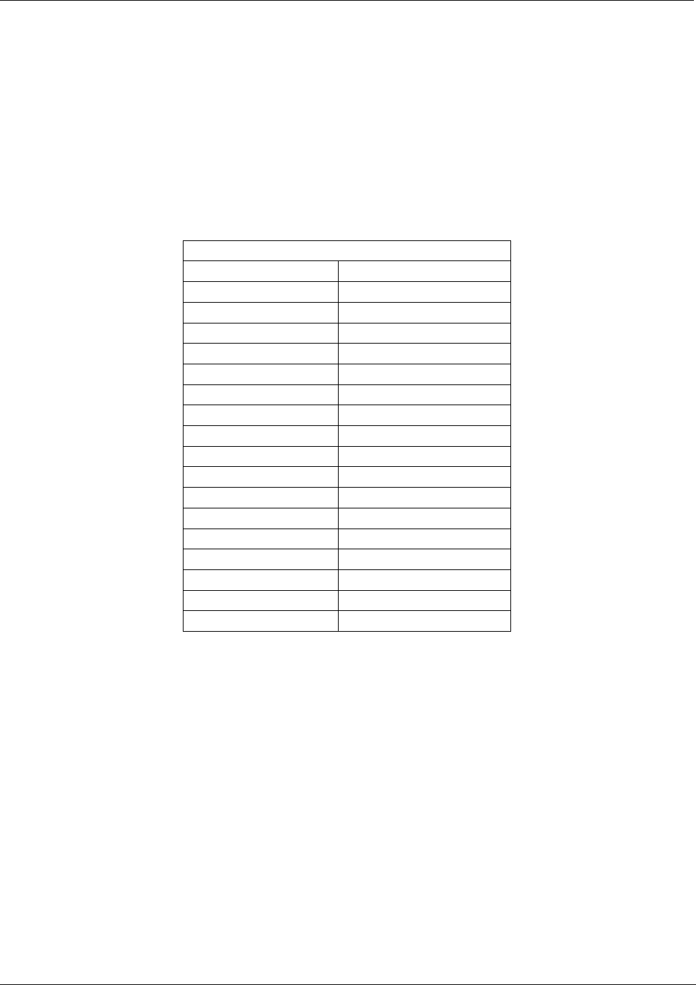
Table 6-2: T703/T703U Gas Pressure to Output Flow conversion Table
T703 REGULATOR PRESSURE TO OUTPUT FLOW
PSIG LPM
0 0.000
1 0.676
2 1.214
3 1.659
4 2.071
5 2.463
6 2.816
7 3.178
8 3.536
9 3.851
10 4.166
15 5.744
20 7.282
25 8.755
30 10.254
35 11.695
40 13.146
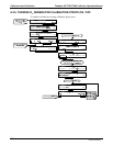
The calculated OUTPUT FLOW value is viewable on the instrument’s front panel
using the OUTPUT FLOW test function and can be output via the T703/T703U’s
TEST CHANNEL using the OUTPUT FLOW function.
07223C DCN6572