


Teledyne API T703/T703U Calibrator Operation Manual General Troubleshooting & Service
165
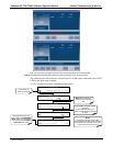
8.1.2. FAULT DIAGNOSIS WITH TEST FUNCTIONS
In addition to being useful predictive diagnostic tools, the test functions viewable from
the calibrator’s front panel can be used to isolate and identify many operational
problems when combined with a thorough understanding of the calibrator’s Theory of
Operation (see Section 9).
The acceptable ranges
for these test functions are listed in the “Nominal Range” column
of the calibrator Final Test and Validation Data Sheet shipped with the instrument.
Values outside these acceptable ranges indicate a failure of one or more of the
calibrator’s subsystems. Functions whose values are still within the acceptable range
but have significantly changed from the measurement recorded on the factory data sheet
may also indicate a failure.
A worksheet has been provided in Appendix C to assist in recording the value of these
Test Functions.
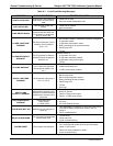
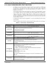
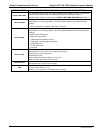
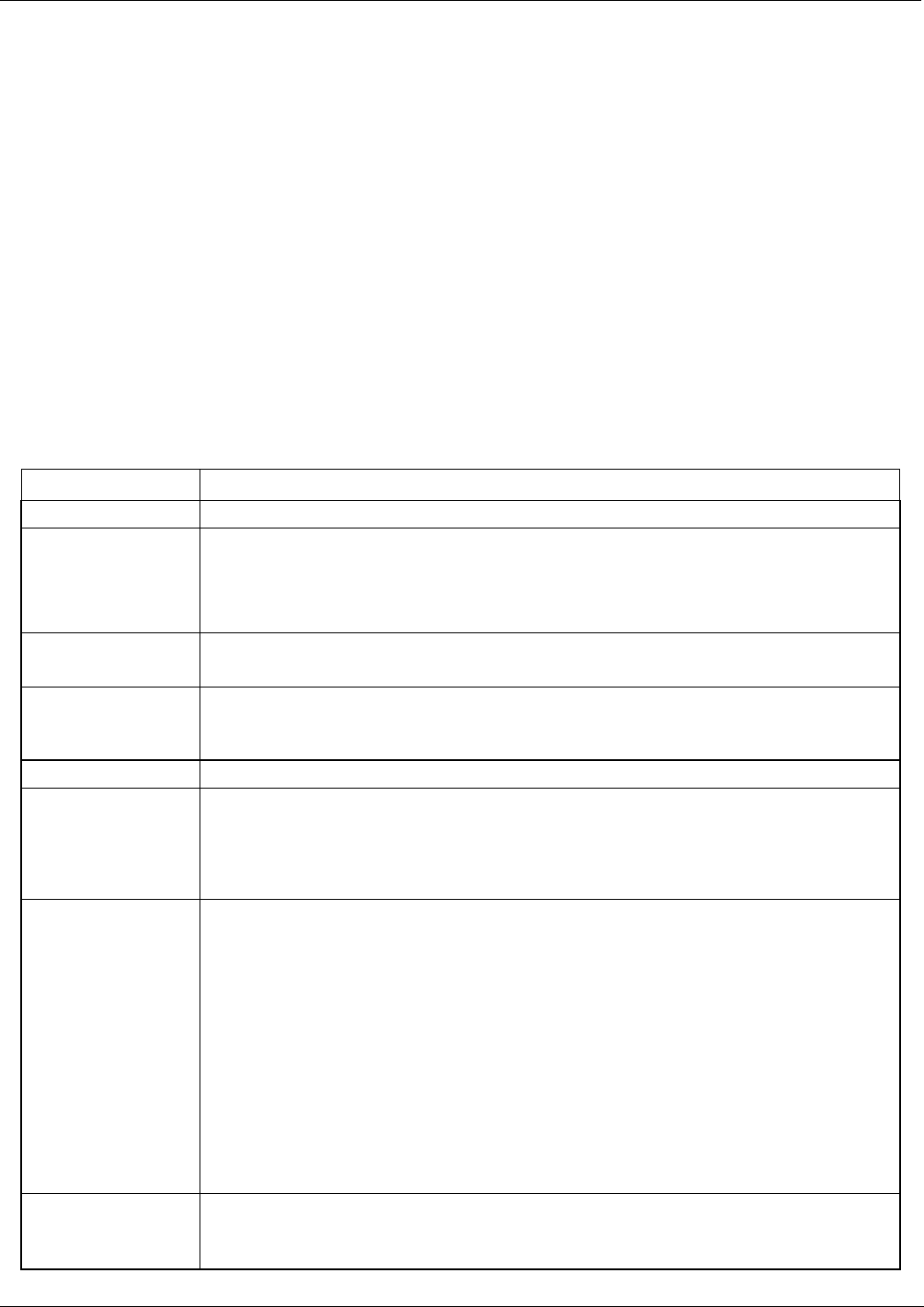
Table 8-2 contains some of the more common causes for these values to be out of range.
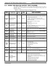
Table 8-2: Test Functions - Indicated Failures
TEST FUNCTION DIAGNOSTIC RELEVANCE AND CAUSES OF FAULT CONDITIONS.
O3 GEN REF
1
Possible causes of faults are the same as O3 GEN REFERENCE WARNING from Table 8-1
OUTPUT FLOW
Gas flow problems directly affect the concentration accuracy of the O
3
calibration gases.
This number is computed using data from the calibrator’s
- Check for Gas Flow problems.
- Check the pressure regulator
O3 GEN DRIVE
Check the O
3
generator heater and temperature sensors
Possible causes of faults are the same as O3 GEN LAMP TEMP WARNING
from Table 8-1
O3 LAMP TEMP
Incorrect Lamp temperature can affect the efficiency and durability of the O
3
generators UV
lamp.
Possible causes of faults are the same as O3 GEN LAMP TEMP WARNING from Table 8-1
REG PRESSURE
Same as REGULATOR PRESSURE WARNING from Table 8-1
BOX TEMP
If the Box Temperature is out of range, make sure that the:
Box Temperature typically runs ~7C warmer than ambient temperature.
- The Exhaust-Fan is running
- The there is sufficient open space to the side and rear of instrument to allow adequate
ventilation.
PHOTO MEASURE
&
PHOTO REFERENCE
If the value displayed is too high the UV Source has become brighter. Adjust the variable
gain potentiometer on the UV Preamp Board in the optical bench.
If the value displayed is too low:
- < 100mV – Bad UV lamp or UV lamp power supply.
- < 2000mV – Lamp output has dropped, adjust UV Preamp Board or replace lamp.
If the value displayed is constantly changing:
- Bad UV lamp.
- Defective UV lamp power supply.
- Failed I
2
C Bus.
If the PHOTO REFERENCE value changes by more than 10mV between zero and
span gas:
- Defective/leaking switching valve.
PHOTO FLOW
Gas flow problems directly affect the accuracy of the photometer measurements and
therefore the concentration accuracy of cal gas mixtures involving O
3
and GPT mixtures.
- Check for Gas Flow problems.
07223C DCN6572