


Teledyne API T703/T703U Calibrator Operation Manual Principles of Operation
195
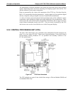
9.2.2.1. Disk On Module (DOM)
The DOM is a 44-pin IDE flash chip with a storage capacity up to 256 MB. It is used to
store the computer’s operating system, the Teledyne API firmware, and most of the
operational data.
9.2.2.2. Flash Chip
This non-volatile, embedded flash chip includes 2MB of storage for calibration data as
well as a backup of the calibrator’s configuration. Storing these key data onto a less
frequently accessed chip significantly decreases the chance of data corruption.
In the unlikely event that the flash chip should fail, the calibrator will continue to
operate with just the DOM. However, all configuration information will be lost,
requiring the unit to be recalibrated.
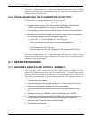
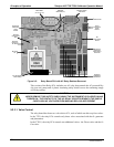
9.2.3. RELAY PCA
The relay board is one of the central switching and power distribution units of the
calibrator. It contains power relays, valve drivers and status LEDs for all heated zones
and valves, as well as thermocouple amplifiers, power distribution connectors and the
two switching power supplies of the calibrator. The relay board communicates with the
motherboard over the I
2
C bus. Its status indicators and components can be used for
troubleshooting power problems and valve or heater functionality.
Generally, the relay PCA is located in the right-rear quadrant of the calibrator and is
mounted vertically on the backside of the same bracket as the instrument’s DC power
supplies, however the exact location of the relay PCA may differ from model to model.
07223C DCN6572