


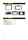

Page 138 AD-4402
12.3.
12.3.12.3.
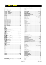
12.3. Index
IndexIndex
Index
#.....................................................................137
#Tot............................................................137
[Control I/O] - [Input]
..........................................121
[Control I/O] - [Output]
.......................................123
[General] - [Others]
...........................................111
[General] - [Sub-display]
....................................109
[General] - [Weighing]
........................................107
[OP-01]
............................................................127
[OP-02]
............................................................128
[OP-03]
............................................................129
[OP-04]
............................................................129
[OP-05]
............................................................131
[OP-07]
............................................................132
[Sequence] - [Basic]
..........................................114
[Sequence] - [Control]
........................................115
[Sequence] - [Safety]
.........................................120
[Sequence] - [Setpoint]
.......................................119
[Sequence] - [Timer]
..........................................117
[Sequence] - [Total]
............................................119
[Serial] - [Current loop]
.......................................126
[Serial] - [RS-485]
.............................................125
key.............................................................8
, CODE RECALL key...........................17
, ENTER key..............................8, 21, 22
, ESC key........................................8, 21, 22
, F1 key, F3 key .............................7, 112
, F2 key, F4 key .............................7, 112
, SHIFT key............................................7
. Standby indicator ..........................................9
, tare key................................................8
, zero key ...............................................8
01 f ...............................................................127
02 f ...............................................................128
03 f ...............................................................129
04 f ...............................................................129
05 f ...............................................................131
07 f ...............................................................132
0Band .........................................................137
0T..................................................................137
1n f ...............................................................122
2 wires........................................................75, 89
4 wires..............................................................89
accumulation....................................................69
accumulation print mode ..................77, 83, 87
actual load calibration ...................................20
ADC...............................................................137
AFFC ............................................................137
alarm ................................................................70
analog output............................................94, 132
ASCII code .....................................................138
auto print mode ................................. 77, 83, 87
automatic program mode .................................38
backuped RAM.................................................72
batch weighing ...........................................25, 35
baud rate ....................................... 75, 83, 89, 92
BCD output...............................................84, 127
BCD terminals ..................................................85
Brate .........................................................137
buzzer..............................................................112
calibration.........................................................20
capacity ......................................................13, 20
category address............................................105
CERR1 ...........................................................24
CERR10.........................................................24
CERR11.........................................................24
CERR2 ...........................................................24
CERR3 ...........................................................24
CERR4 ...........................................................24
CERR6 ...........................................................24
CERR7 ...........................................................24
CERR8 ...........................................................24
CERR9 ...........................................................24
Cl f................................................................126
clear..................................................................69
command mode..............................................77
communication modes .....................................77
comparison.................................................61, 63
comparison output............................................60
compensation.............................................58, 59
compensation sequence ..................................43
Consumer programmed control .....................114
current loop ......................................................83
customer programmed control ...................35, 60
CZ...............................................................9, 137
D.....................................................................137
D.FLOW .............................................................9
data length..................................... 75, 83, 89, 92
decimal point ....................................................20
delete................................................................69
DFlow .........................................................137
digital span .....................................................20
discharge sequence .........................................47
division .............................................................20
earth terminal .....................................................6
emergency........................................................56
emergency stop................................................56
entrance sequence...........................................45
error code.........................................................24
error message ..................................................70
error signal .......................................................56
Eval ............................................................137
EXC-.................................................................12
EXC+................................................................12