


PCS -1/1P
3-207-456-12 (1)
I:\3207456121PCS1WW\09OTH.FM
masterpage:Left
155Location and Function of Parts and Controls
Appendix
Location and
Function of Parts
and Controls
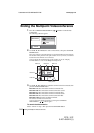
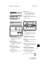
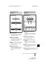
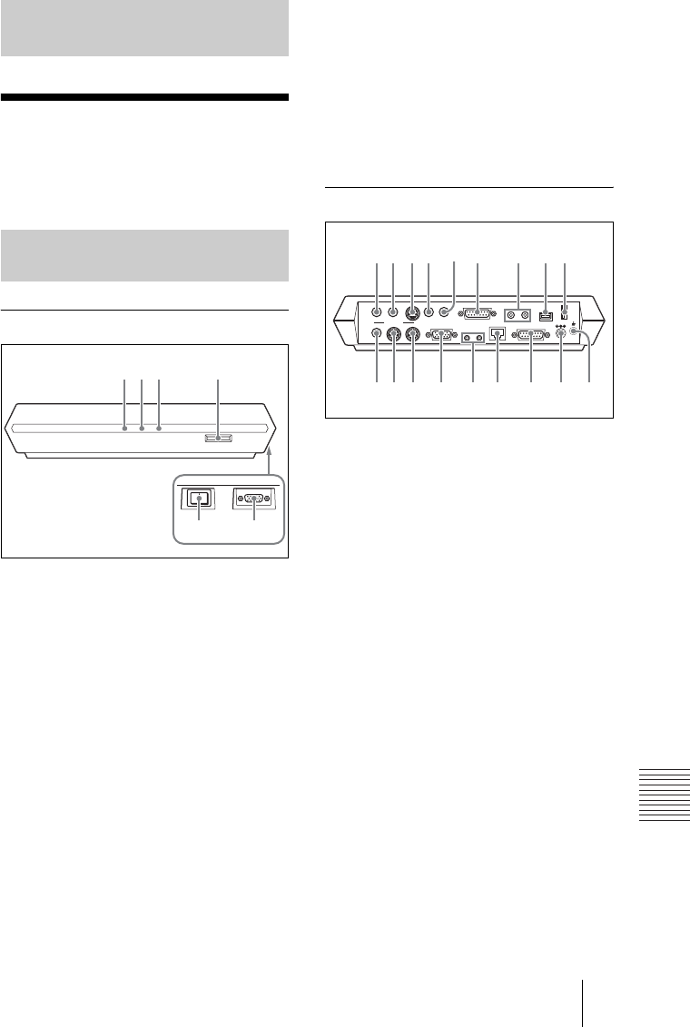
Front/Right side
a ON LINE indicator
Blinks during dialing or answering and
lights in blue when connection is
completed. It turns off when the system
is disconnected.
b POWER indicator
Lights in green when the power switch is
set to on (@). Lights in orange when the
Communication Terminal is set to
standby mode.
c LAN ALERT indicator
Lights in yellow when packet error
(loss) or link error occurs during
communication.
d Memory Stick slot
Insert a “Memory Stick” (not supplied)
into this slot.
e Power switch
Turns on/off the Communication
Terminal. The power is on when the
switch is set to the @ side and off when
the switch is set to the a side.
f AUX CONTROL connector (D-sub
9-pin)
Used for service.
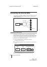
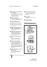
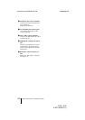
Rear
a AUDIO OUT (MIXED) jack (phono
jack)
Used when recording the sound to
minute a conference. The mixed sounds
of a local and remote parties are output
from this jack.
b AUDIO OUT jack (phono jack)
Connect to the audio input of the TV
monitor.
c VIDEO IN AUX 1 connector (mini
DIN 4-pin)
Connect to the video output of external
video equipment.
d VIDEO IN AUX 2 jack (phono jack)
Connect to the video output of external
video equipment.
e AUDIO IN jack (phono jack)
Connect to the audio output of the
optional VCR or audio equipment.
f CAMERA UNIT connector
Connect to the TERMINAL connector
on the rear of the Camera.
Appendix
PCS-P1/P1P Communication
Terminal
ON LINE POWER LAN ALERT
12 3 4
56
DC 19.5V
AUDIO OUT
AUDIO IN
AUX1–
VIDEO IN
–AUX2
CAMERA UNIT MIC
(PLUG IN POWER)
ISDN UNIT WHITE
BOARD
(MIXED)
AUX
MAIN
–
MONITOR
–
SUB
VIDEO OUT
RGB OUT DSB
IR OUT
100BASE-TX
10BASE-T
12
1 2
1
q
;
q
a
q
s
q
d
q
f
q
g
q
h
q
j
q
k
23 6 7 89
54