


PCS -1/1P
3-207-456-12 (1)
I:\3207456121PCS1WW\09OTH.FM
masterpage:Left
159Location and Function of Parts and Controls
Appendix
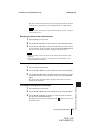
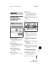
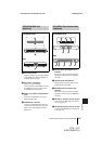
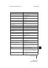
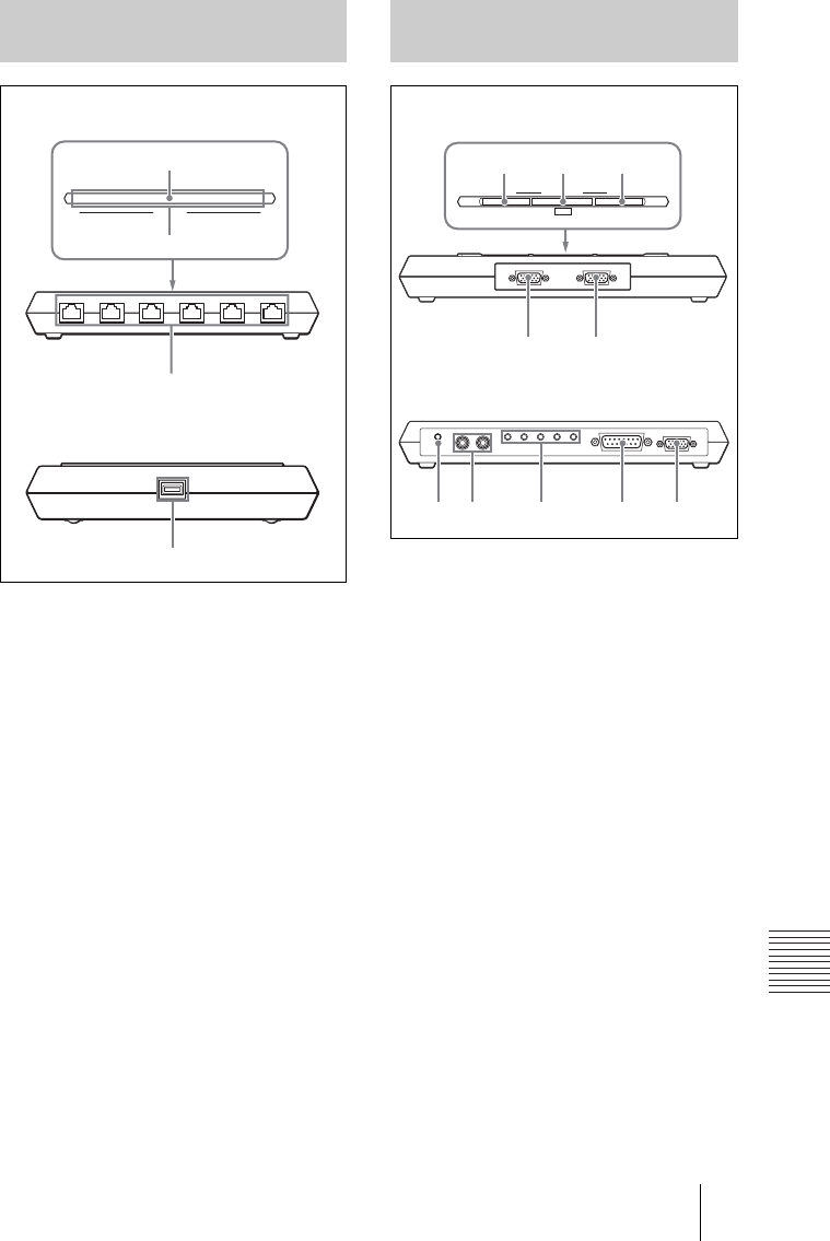
a STATUS indicator
Lights in orange when power is supplied
to the ISDN Unit. When initializing is
complete, blinks in green.
b STATUS 1-6 indicators
Lights in orange when link
synchronization of each ISDN connector
is established. Lights in yellow when
each ISDN line is connected.
c ISDN 1-6 terminals (8-pin modular
jack)
Connect to the ISDN lines using the
ISDN modular cable.
d TERMINAL connector
Connect to the ISDN UNIT connector
on the Communication Terminal with
the interface cable supplied with the
ISDN Unit.
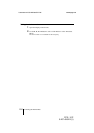
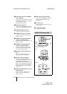
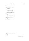
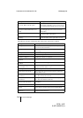
a RGB A input select button and
indicator
Selects the video input from the video
equipment connected to the RGB IN A
connector.
b SEND button and indicator
Sends the selected input picture to the
Communication Terminal.
c RGB B input select button and
indicator
Selects the video input from the video
equipment connected to the RGB IN B
connector.
d RGB IN A connector (D-sub 15-pin)
Connects to the RGB output connector
on a computer, etc.
e RGB IN B connector (D-sub 15-pin)
Connect to the RGB output connector on
a computer, etc.
PCS-B768 ISDN Unit
(Optional)
123456
123456
STATUS
1
2
3
4
Front/Upper panel
Rear
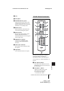
PCS-DSB1 Data Solution Box
(Optional)
RGB IN BRGB IN A
RGB A
SEND
RGB SELECT
RGB B
123
45
67 8 9 q
;
AUX MIC 1 MIC 2 MIC 3 MIC 4 MIC 5 TERMINAL RGB OUTOUTLINE OUT IN
Front/Upper panel
Rear