


156 Location and Function of Parts and Controls
PCS -1/1P
3-207-456-12 (1)
I:\3207456121PCS1WW\09OTH.FM
masterpage:Left
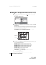
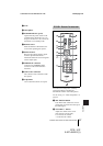
g MIC1/MIC2 (PLUG IN POWER)
jacks (minijack)
Connect to the optional PCS-A1 or PCS-
A300 microphone. Power is supplied to
the microphone from the
Communication Terminal.
h ISDN UNIT connector
Connect to the TERMINAL connector
on the optional PCS-B768 ISDN Unit.
i WHITE BOARD connector
Connect to the optional mimio Xi.
j VIDEO OUT AUX jack (phono)
Connect to the video input of the TV
monitor or VCR.
k VIDEO OUT MONITOR MAIN
connector (mini DIN 4-pin)
Connect to the S-video input on the TV
monitor or VCR.
l VIDEO OUT MONITOR SUB
connector (mini DIN 4-pin)
Connect to the S-video input on the
second TV monitor when the system
uses the dual monitor mode.
m RGB OUT connector (D-sub 15-
pin)
Connect to the RGB input of the
optional projector or display unit.
n IR OUT 1/2 jacks (minijack)
Connect the supplied IR repeater.
Connect the IR repeater for the monitor
connected to the VIDEO OUT
MONITOR MAIN connector to the IR
OUT 1 jack, and the IR repeater for the
monitor connected to the VIDEO OUT
MONITOR SUB connector to the IR
OUT 2 jack.
o 100BASE-TX/10BASE-T connector
(8-pin modular)
Used to conduct a conference via a
LAN. Connect to a hub using the
category 5 cable.
p DSB connector (D-sub 15-pin)
Connect to the TERMINAL connector
on the optional PCS-DSB1 Data
Solution Box.
q DC 19.5V jack
Connect the supplied PCS-AC195 AC
power adaptor.
r U (ground) terminal
Connect a ground wire.
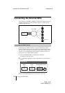
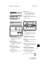
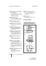
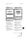
PCS-C1/C1P Camera Unit
4
3
5
1
2
TERMINAL VISCA OUT
67
8
Front
Rear
Bottom