


20 System Connections
PCS-1/1P
3-207-456-12 (1)
I:\3207456121PCS1WW\03OVR.FM
masterpage:Left
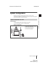
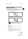
• Do not connect/disconnect the camera cable or the interface cable with the power on.
Doing so may damage the Camera Unit, Communication Terminal or ISDN Unit.
• Used with the PCS-B768 ISDN Unit for the first time, the Communication Terminal
may automatically upgrade the software of the ISDN Unit. While the upgrading
message is displayed on the monitor screen, be sure not to turn off the Communication
Terminal. Doing so may cause malfunction of the system.
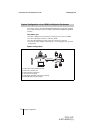
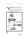
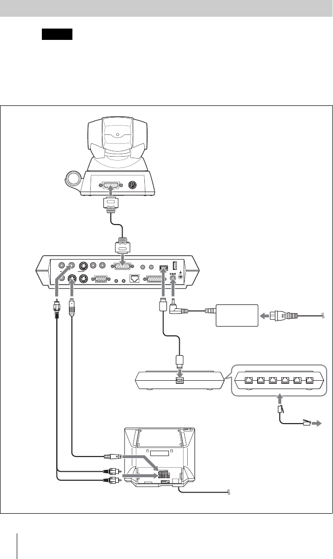
System Connection via an ISDN
Notes
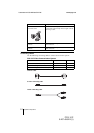
123456
DC 19.5V
AUDIO OUT
AUDIO IN
AUX1–
VIDEO IN
–AUX2
CAMERA UNIT MIC
(PLUG IN POWER)
ISDN UNIT WHITE
BOARD
(MIXED)
AUX
MAIN
–
MONITOR
–
SUB
VIDEO OUT
RGB OUT DSB
IR OUT
100BASE-TX
10BASE-T
12
1 2
TERMINAL VISCA OUT
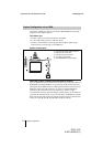
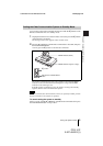
PCS-C1/C1P Camera Unit
to TERMINAL
PCS-P1/P1P
Communication
Terminal
Camera cable*
Audio
connecting
cable*
S-video
connecting
cable*
Power cord*
to CAMERA UNIT
to AUDIO
OUT
to VIDEO
OUT
MONITOR
MAIN
to S-video
input
to audio input
TV monitor**
to a wall outlet
to DC19.5V
PCS-AC195
AC adaptor
to a wall outlet
* supplied
**not supplied
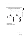
Interface cable
(supplied with the PCS-B768)
to ISDN
UNIT
to
TERMINAL
PCS-B768 ISDN Unit**
to ISDN
Front
to ISDN 1-6
ISDN modular
cable**