7 - 7
MELSEC-F
FIXED BUFFER COMMUNICATION (WITH THE NO PROCEDURE
CONTROL METHOD)
7
7 - 7
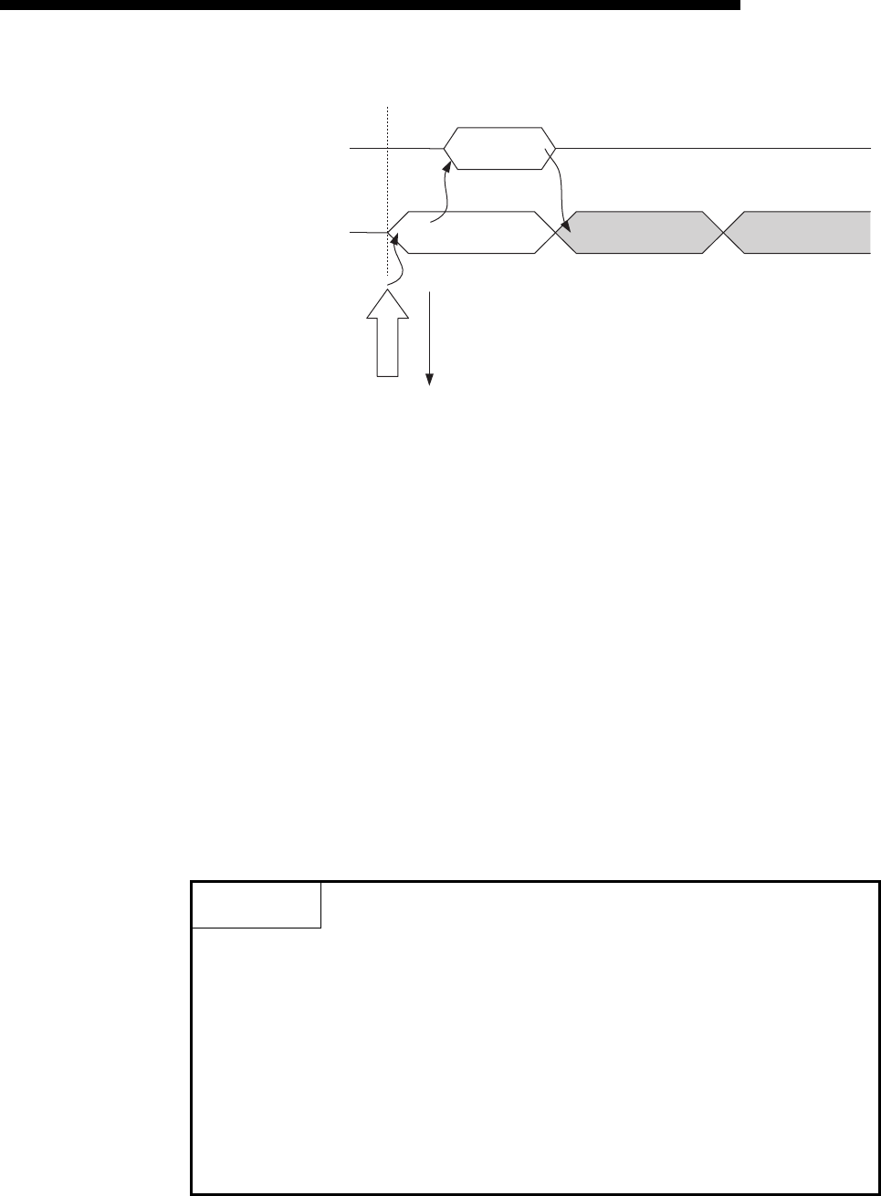
1) Upon receiving data from the designated external device (set in the open
processing), the Ethernet module processes the following.
• Stores the received data to the fixed buffer (No. 2) area.
(Area beginning from the head address of the target fixed buffer + 1)
• Stores the data length to the head address area of the target fixed
address
(*1)
• Fixed buffer communication receive results (BFM#1611) : 0001H
• Fixed buffer receive status signal (BFM#20485 b1) : ON
*1 The received data length is expressed by a byte count.
When an odd number of data bytes is received, the last byte of
received data is stored at the lower byte of the last data storage area.
(The higher byte becomes a non-constant value.)
2) Execute the FROM instruction to read out the receive data length and
receive data to the PLC.
3) Execute the TO instruction to write "0002
H" in the fixed buffer
communication receive results (BFM#1611).
4) Result of the receiving processing is indicated.
POINT
(1) The destination setting (see Section 5.5) for a connection whose parameters
are set in FX Configurator-EN becomes valid when the open completion
signal (BFM#20480 corresponding bit) of the Ethernet module switches from
off to on.
(2) When data is received and the data in the buffer memory's fixed buffer is set,
BFM #1610 to 1617 is set to "0001
H".
(3) At abnormal data receiving, each buffer memory status becomes as follows.
• Fixed buffer receive completion signal (BFM#20485 b1) remains off.
• Fixed buffer communication receive results (BFM#1611): 0008
H
• Data is not stored in the fixed buffer (No.2) area.
Read the word count
for the received data
and receive data
FROM
instruction
Notice the receive status
and receive completion
of the fixed buffer
BFM#1611
R
BFM#1611=0001
H
Data receiving
ACK(only in TCP)
1)
2)
Data
receiving
W
0002
H
3)
R
0004
H(Success)
/0008
H(Error issued)
4)


