


9 - 4
MELSEC-F
WHEN COMMUNICATING DATA USING THE MC PROTOCOL9
9 - 4
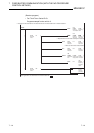
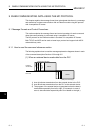
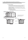
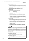
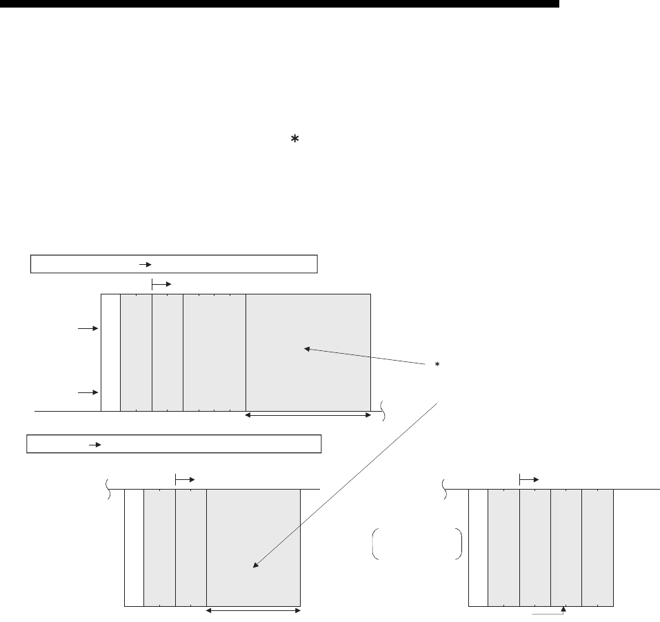
(2) Control procedure
The following diagrams illustrate the control procedure for communicating with
the MC protocol and the order of data items in the application data field.
The header section shown in the message explanation diagram of this section
corresponds to the portion of the message explanation diagrams indicated in
Subsection 9.3.2 and later.
See Subsection 9.1.3 regarding the content of data items in the message format
and data specification method.
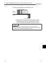
(a) Communication in ASCII code
1) When reading data from the local station PLC at the external device side
External device side PLC side (Command message)
(Data name)
(Example)
Header
0
0
FF
-
A
Subheader
PC No.
Monitoring
timer
Character area A
The contents and arrangement of the data items in
the text differs according to the function to use.
See the sections explaining functions found in
Subsection 9.3.2 and after for details
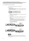
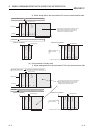
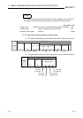
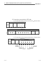
PLC side
Text (Command)
External device side (Response message)
(Normal completion)
Text (Response)
Header
Subheader
Complete code
Character area B
(Abnormal completion)
Text (Response)
Header
Subheader
Complete code
Abnormal code
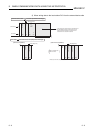
When complete code
5B
H is returned
30H
38H
80
HL
00
Exists only when the complete code is "5B."
38H
80
HL
5B
HL
1200
30
H
H
L
H
L
0
00
30
H 30H 30H
46H
46H
41H
30H
30H 30H
30H
30H 30H35H 42H
31H
32H
-