


9 - 33
MELSEC-F
WHEN COMMUNICATING DATA USING THE MC PROTOCOL9
9 - 33
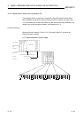
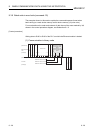
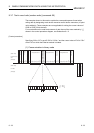
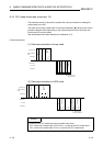
9.3.7 Test in word units (random write) (command: 05)
The examples shown in this section explain the command/response format when
writing data by designating word device memories and bit device memories (16 point
units) arbitrarily. These examples are not applicable for writing the current values of
C200 to C255 (32-bit devices).
For more details on the order and contents of data items of the areas marked by " "
shown in the control procedure diagram, see Subsection 9.1.2.
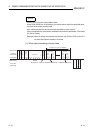
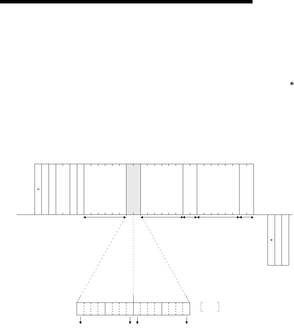
[Control procedure]
Specifying Y20 to Y37 to on/off, R26 to "1234
H," and the current value of C18 to "50H"
at the PLC on which the Ethernet module is loaded.
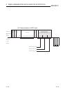
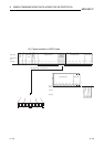
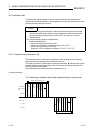
(1) Communication in binary code
Current value of CN18 50
H
1234
H
Y30Y37Y20Y27
0010100101111011
Y20 R26
1....ON
0....OFF
05
H
FF
H
0A
H
03
H
00
H
80
H
00
H
00
H
00
H
20
H
59
H
29
H
7B
H
1A
H
00
H
00
H
00
H
20
H
52
H
34
H
12
H
12
H
00
H
00
H
00
H
4E
H
43
H
50
H
00
H
00
H
85
H
00
H
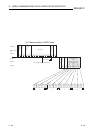
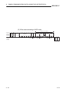
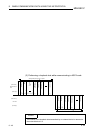
LL-HLH---HL-HL--- HL- HL--- H
(Data name)
External device
side
(Example)
(Data name)
PLC side
(Example)
Subheader
PC No.
Number of device points
Monitoring
timer
Designated device
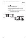
Subheader
Complete code
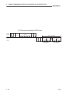
to to
Designated device Designated device
Device data
(ON/OFF designation)
Device data
Device data