


4 - 6
MELSEC-F
SETTINGS AND PROCEDURES PRIOR TO OPERATION4
4 - 6
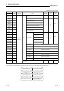
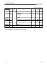
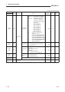
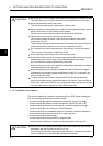
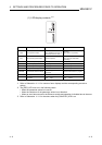
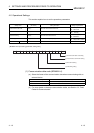
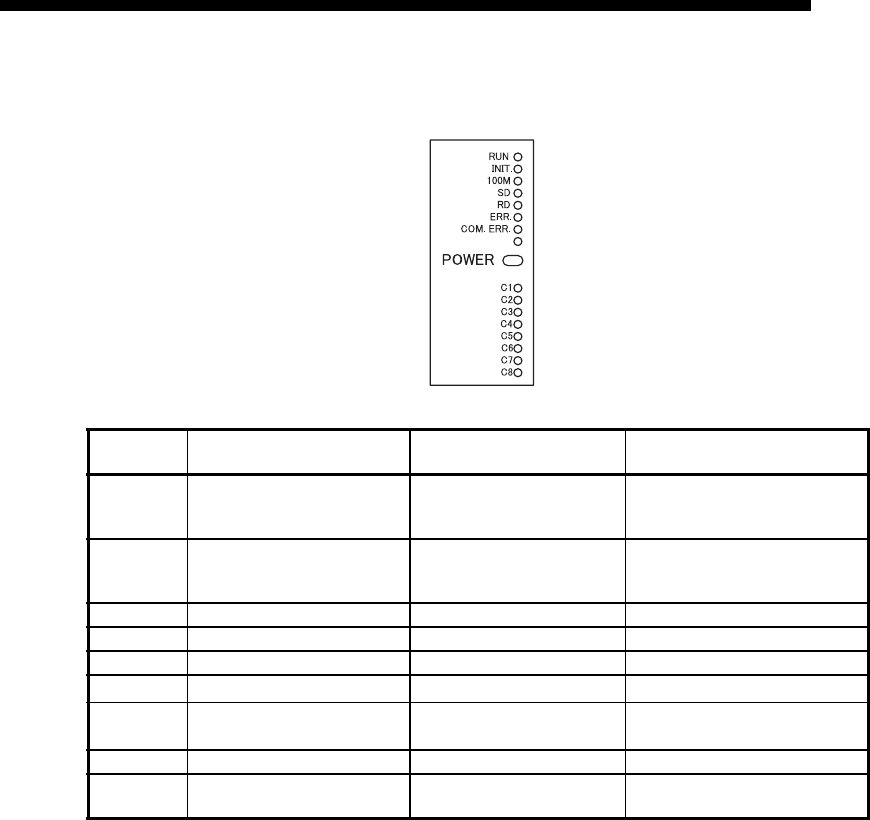
(1) LED display contents
(*1)
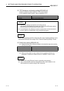
*1 Refer to Subsection 11.1.1 for causes of error displays and the corresponding corrective
actions.
*2 The [ERR.] LED turns on in the following cases:
• When the parameter written is incorrect.
• When the checksum of the parameter written is not identical.
• When an error has occurred in the Ethernet module and operation is disabled due to the error.
*3 Refer to Subsection 11.1.1 for the status when the [COM.ERR.] LED is on.
LED name Display description When the LED is on When the LED is off
RUN Normal operation display
Normal
(when FROM/TO instruction can
be executed from PLC side)
Abnormal
(when WDT is in operation)
INIT. Initial processing status display Normal completion
Not processed
(when execution failed initial
processing)
100M Transmission speed display 100Mbps 10Mbps/When not connected
SD Data sending display Data being sent Data not being sent
RD Data receiving status display Data being received Data not being received
ERR. Setting abnormal display
Abnormal
*2
Normal setting
COM.ERR. Communication abnormal display
Communication abnormal
occurrence
*3
Normal communication in progress
POWER Module power status Power is on Power is off
C1 to C8
TCP/IP, UDP status of the
connections
TCP/IP : Connection Established
UDP : Open
TCP/IP : Connection not Established
UDP : Closed