9 - 13
MELSEC-F
WHEN COMMUNICATING DATA USING THE MC PROTOCOL9
9 - 13
(2) Data communication using binary code
(a) When reading to or writing from the bit device memory
The bit device memory can be read and written in bit units (one device point)
or word units (16 device points).
How data is transmitted in each case is explained below.
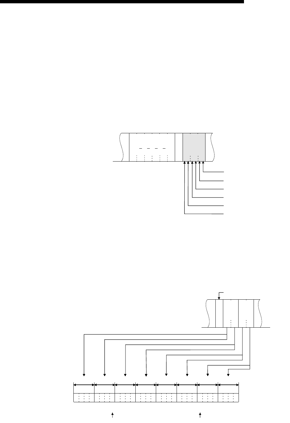
1) Bit units (one point)
In case of bit units, four bits designate one point and the bit device
memory is handled from the designated head device for the number of
designated device points sequentially from the left. They are expressed
as "1" if the device is ON or "0" if the device is OFF.
(Example)
Indicating the ON/OFF status of five points from M10
2) Word units (16 points)
In case of word units, one bit designates one point and the bit device
memory is handled from the designated head device for the number of
designated device points sequentially from the left. They are expressed
in 16-point units in the order, low byte (L: bits 0 to 7) to high byte (H: bits
8 to 15).
(Example)
Indicating the ON/OFF status of 32 points from M16
0A
H
L
00
H
00
H
H
20
H
00
H
40
H
05
H
10
H
10
H
10
H
Head
device
Data
Expressed by dummy when the point is
an odd number
Indicates that M14 is ON
Indicates that M13 is OFF
Indicates that M12 is ON
Indicates that M11 is OFF
Indicates that M10 is ON
Device point
02
H
12
H
AB
H
CD
H
34
H
B7
00010010101010111100
B6 B5 B4 B3 B2 B1 B0
B15
B14
B13
B12
B11B10B9B8
110100110100
B7 B6 B5 B4 B3 B2 B1 B0
B15
B14
B13
B12
B11B10B9B8
12ABCD34
23 22 21 20 19 18 17 16 31 30 2928 27 26 25 24 39 38 37 36 35 34 33 32 47 46 45 44 43 42 41 40
LH
Data
The device point is "02" in 16-point units.
1: Indicates ON
0: Indicates OFF
MMMMMMMMMMMMMMMM MMMMMMMM MMMMMMMM
34CD
H
LH
Data
AB12
H
Device point
Head End
