


3 - 8
MELSEC-F
SPECIFICATIONS3
3 - 8
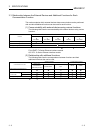
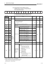
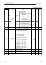
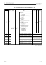
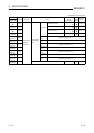
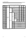
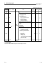
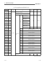
3.6 List of Applications and Assignments of the Buffer Memory
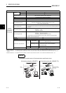
Data transmission/reception between Ethernet Module and PLC is performed via the
Ethernet Module buffer memory (hereinafter called BFM).
Reading/writing data in the buffer memory from the PLC must be performed by the
FROM/TO instructions (instructions that can access BFM).
In addition, the initial value of the buffer memory or the internally stored value is
written when the power is turned on.
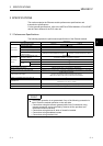
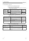
(1) Configuration of the buffer memory
Buffer memory consists of a user area and a system area, as listed below.
(a) User areas
1) The areas where the user writes/reads data.
2) A user area consists of a parameter area for initial processing and data
communication, an area for data communication, and an area for storing
communication status and communication error data.
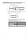
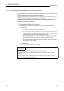
3) Reading/writing data to the user area should be performed according to
the instructions in the corresponding detailed explanation section.
Data communication may take longer if continually executed; therefore,
execute only when needed.
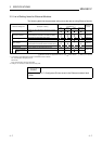
(b) System areas
The areas used by the Ethernet module
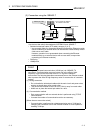
Important
Do not write data in the "system areas" of the buffer memory.
If data is written to any of the system areas, the PLC system may not operate
properly.
When writing a value to the buffer memory including "System Area," pay close
attention not to change the system bit.