


3 - 9
MELSEC-F
SPECIFICATIONS3
3 - 9
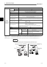
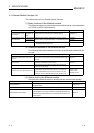
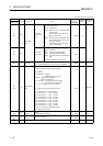
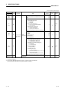
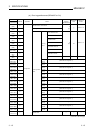
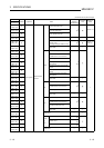
(2) Assignments of the buffer memory
A buffer memory consists of 16 bits per address.
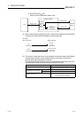
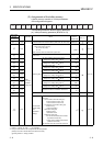
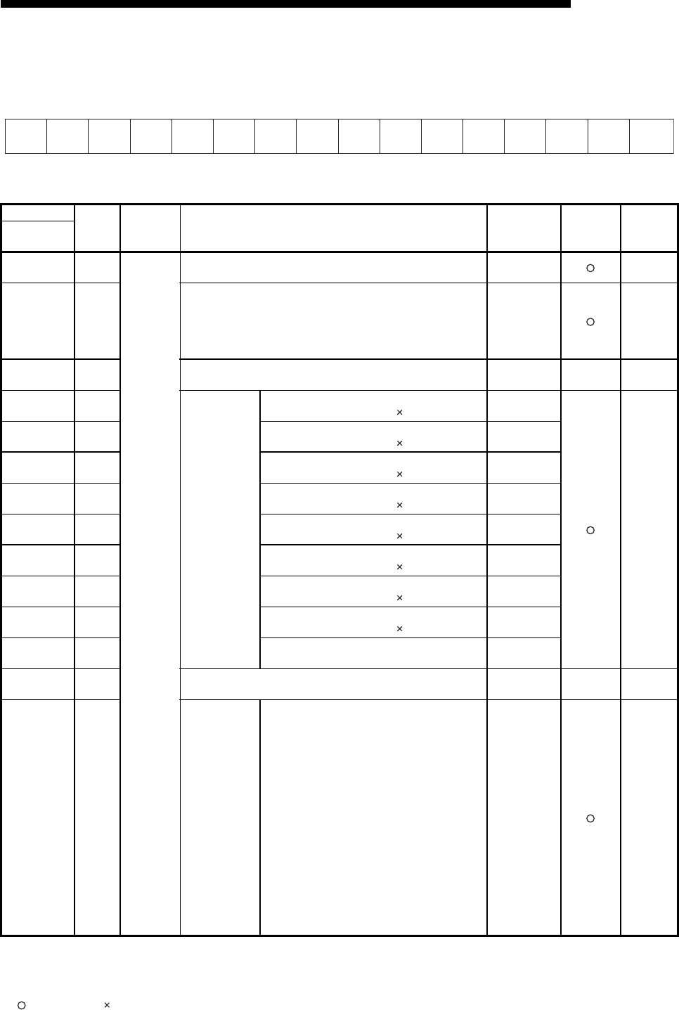
<Bit configuration diagram>
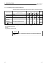
The following shows the buffer memory addresses.
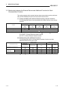
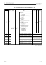
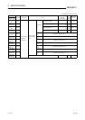
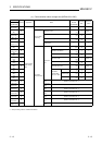
(a) Initial processing parameter (BFM #0 to 31)
(Continues on the next page)
*1 Attribute R : Read, W : Write, — : Use prohibited
*2 Saving to Flash ROM from FX Configurator-EN allowed/prohibited
(Settings are saved in the flash ROM of the Ethernet module.)
: Setting allowed : Setting prohibited
BFM number
Attribute
*
1
Application Name
Initial value
Decimal
(Hexadecimal)
Flash ROM
save (*
2
)
Reference
section
Decimal
(Hexadecimal)
0 to 1
(0 to 1
H)
R/W
Initial
processing
parameter
setting area
Local station Ethernet module IP address (Initial value 192.168.1.254)
3232236030
(C0A801FE
H)
Section 4.6
2
(2
H)
R/W
Special function settings
• Router relay function (b5, b4)
00: Do not use (initial)
01: Use
Bits other than above are reserved for system use.
0
(0000
H)
Section 5.3
3
(3
H)
— System area — — —
4
(4
H)
R/W
Monitoring timer
TCP ULP (existence function) timer value
Setting time = setting value 500 ms
60
(3C H)
Section 5.2
5
(5
H)
R/W
TCP zero window timer value
Setting time = setting value 500 ms
20
(14 H)
6
(6
H)
R/W
TCP resend timer value
Setting time = setting value 500 ms
20
(14
H)
7
(7
H)
R/W
TCP end timer value
Setting time = setting value 500 ms
40
(28
H)
8
(8
H)
R/W
IP assembly timer value
Setting time = setting value 500 ms
10
(A H)
9
(9
H)
R/W
Response monitoring timer value
Setting time = setting value 500 ms
60
(30
H)
10
(A
H)
R/W
Destination existence confirmation starting interval
Setting time = setting value 500 ms
1200
(480
H)
11
(B
H)
R/W
Destination existence confirmation interval timer
Setting time = setting value 500 ms
20
(14 H)
12
(C
H)
R/W Destination existence confirmation resend timer
3
(3
H)
13 to 23
(D to 17
H)
— System area — — —
24
(18
H)
R/W
Communication
condition setting
area
(Operational
Settings)
Communication condition setting (Operational Set-
tings) area
• Communication data code setting (b1)
0: Communication in binary code
1: Communication in ASCII code
• TCP Existence confirmation setting (b4)
0: Use the Ping
1: Use the KeepAlive
• Send frame setting (b5)
0: Ethernet frame
1: IEEE 802.3 frame
• Initial timing setting (b8)
0: Do not wait for OPEN (communication
impossible at STOP time)
1:
Always wait for OPEN (communication
possible at STOP time)
Bits other than above are reserved for system use.
0
(0
H)
Section 4.6
b15 b14 b13 b12 b11 b10 b9 b8 b7 b6 b5 b4 b3 b2 b1 b0