


11 - 10
MELSEC-F
TROUBLESHOOTING11
11 - 10
11.3 Checking the error information by the buffer memory batch monitoring function
It is explained here how the Ethernet module errors can be checked from GX
Developer.
Error codes stored in the buffer memory of the Ethernet module can be monitored
using the "Buffer memory batch monitoring" function of GX Developer.
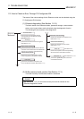
[Operating procedure]
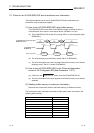
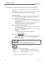
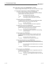
(Step 1) Select [Online] - [Monitor] - [Buffer memory batch] from the GX Developer
menu bar, and start the "Buffer memory batch monitoring" screen.
(Step 2) Enter [Module start address:].
Assign a special module number to each base module following the order
that 0 is assigned to the rightmost module, 1 to the second rightmost module,
and goes same up to 7.
However, for FX
3UC-32MT-LT(-2) which incorporates the CC-Link/LT
function, the first special module will be assigned with No.1.
(Step 3) Enter [Buffer memory start address:].
Enter the buffer memory address to be monitored, using the selected input
format (decimal/hexadecimal).
For a list of the buffer memory addresses where error codes are stored, see
Section 11.4, "Error Code List".
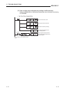
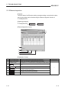
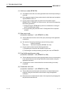
(Example)
When monitoring the initial abnormal code (BFM #105):
Enter "105" + "decimal"
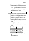
(Step 4) Click the button.
The contents of the buffer memory after the specified address are displayed.
(In case of the above example, the contents of 105
H and succeeding
addresses are displayed.)
NOTE
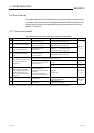
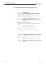
The display format can by modified as follows:
For details, refer to the "Operating Manual" for GX Developer.
POINT
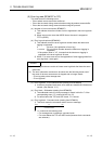
To see if the PLC base module recognizes the FX
3U
-ENET or not, monitor BFM #30.
If BFM #30's value is K7130, the FX3U-ENET is being recognized.
Monitor format : Bits & words/ Multiple bit points/ Multiple word points
Display : 16-bit integer/32-bit integer/real number/ASCII character
Numerical value : Decimal/hexadecimal
Start Monitor