


9 - 23
MELSEC-F
WHEN COMMUNICATING DATA USING THE MC PROTOCOL9
9 - 23
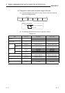
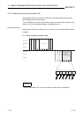
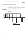
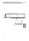
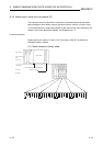
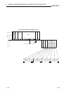
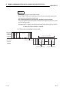
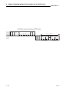
9.3.4 Test in bit units (random write) (command: 04)
The examples shown in this section explain the command/response format when
writing data by designating bit device memories arbitrarily.
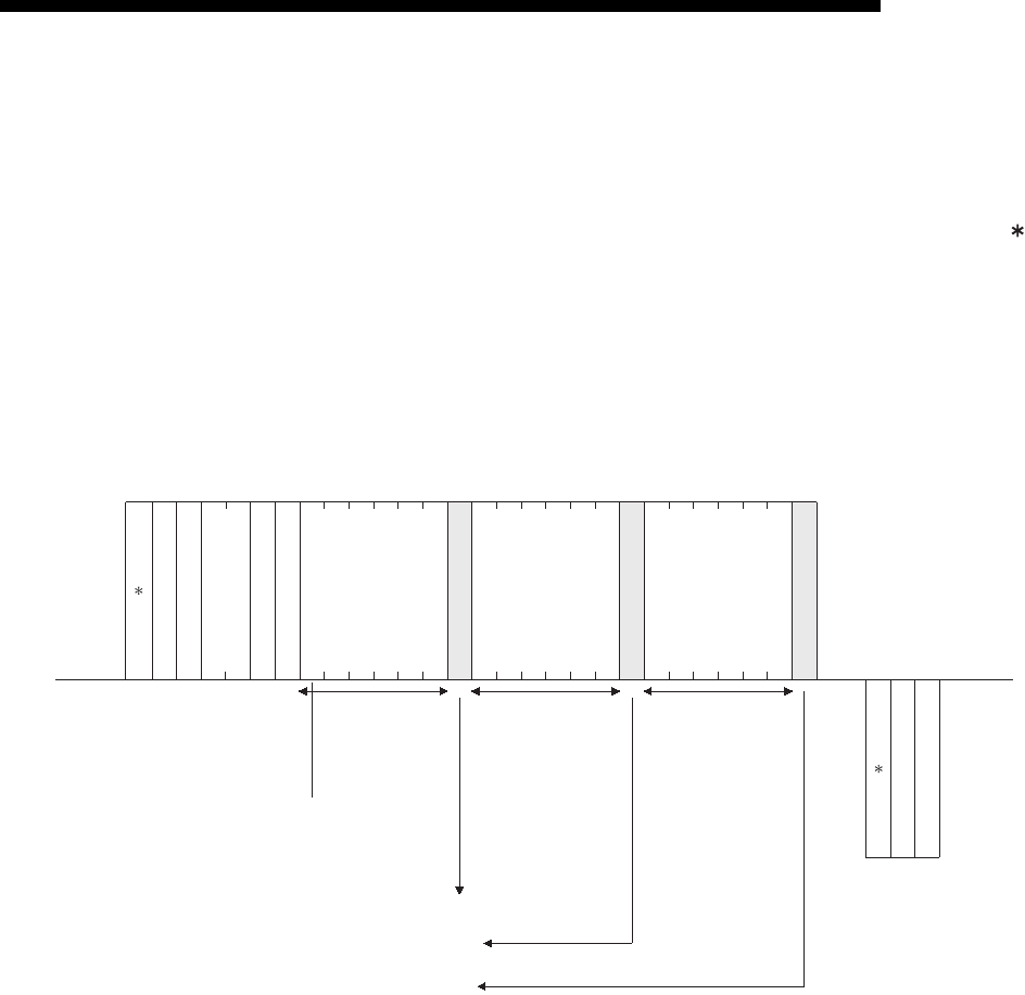
For more details on the order and contents of data items of the areas marked by " "
shown in the control procedure diagram, see Subsection 9.1.2.
[Control procedure]
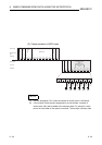
Specifying Y45 to ON, M60 to OFF, and S38 to ON at the PLC on which the Ethernet
module is loaded.
(1) Communication in binary code
H
FF
H
0A
H
00
H
01
H
3C
H
(Data name)
External device
side
(Example)
(Data name)
PLC side
(Example)
4D
H
04
H
Designated deviceDesignated device
03
H
00
H
00
H
00
H
00
H
20
H
59
H
00
H
00
H
00
H
20
H
00
H
26
H
00
H
00
H
20
H
01
H
53
H
ON/OFF designation
L
00
H
25
H
LH LHH
Designated device
84
H
00
H
Y45
(Octadecimal)
M60 S38
Designates to turn Y45 ON.
Designates to turn M60 OFF.
Designates to turn S38 ON.
L
- --- ---- -- --
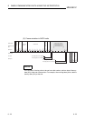
Subheader
PC No.
Number of device points
Monitoring
timer
ON/OFF designation
ON/OFF designation
Subheader
Complete code
45 (Octadecimal) = 25 (Hexadecimal)