


4 - 7 4 - 7
MELSEC-Q
4 SETTING AND PROCEDURE BEFORE OPERATION
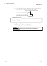
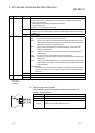
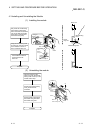
No. Name LED status Description
7
ERR.
1
ON (red) • Station number setting error (other than 1 to 64), mode setting error (set to disabled), or
operating condition setting error (in parameter)
• A station with the same station number exists in the network.
• Parameter data received from the remote master station has an error.
• Watchdog timer error (The RUN LED is off.)
Flashing • An error was detected while the network module was being tested.
• The setting of the mode setting switch or the station number setting switch was changed
during operation.
2
OFF Normal operation
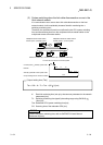
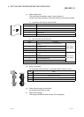
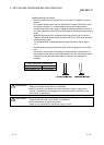
8 L ERR. ON (red) • Watchdog timer error (The RUN LED is off.)
• Communication error (One of the following errors has been occurred.)
CRC : This error occurs due to a fault in the cable or noise.
OVER : This error occurs when the received data is erased before it is written to the
internal memory because the next data is received. The possible error cause is a
hardware failure at the receiver part of the network module.
AB.IF : This error occurs when the number of the bits indicating "1" in the received data
within a frame exceeds the limit or the received data length is shorter than that
defined in the specifications.
TIME : This error occurs when the baton pass is not handed to the host station within the
monitoring time.
DATA : This error occurs when the data with abnormal code is received.
UNDER : This error occurs when the internal processing of the send data was not executed
at a fixed interval.
LOOP : This error occurs when the forward loop or reverse loop line is faulty. The power
of the adjacent station in the direction to the host station is off or the hardware
failure exists on the send station.
<Corrective action>
Check the connector for disconnection, looseness, and IN/OUT misconnection; and
the cable for disconnection, crack, and routing. For details, refer to the network
diagnostics (Section 8.1).
OFF No communication error
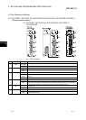
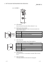
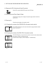
1: When the remote I/O module is used in a redundant power supply system, the cause of failure in
the power supply module can be diagnosed with the status of the REM. LED and ERR. LED.
Power supply module Cause of failure REM. LED ERR. LED
Failure of one module
Input power supply off, fuse blown OFF ON
Internal failure
OFF ON
ON OFF
Failure of both modules
Input power supply off, fuse blown OFF OFF
Internal failure
OFF OFF
OFF ON
ON OFF
The faulty power supply module can be identified in the corresponding error code. (Refer to
Section 8.3.3.)
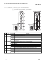
When a remote I/O module of function version C or earlier is used, the ERR. LED remains off
even if one or two power supply modules fail.
Check the failure status of the power supply module with the LEDs of the module. When the
power supply module is mounted on an extension base unit, the failure status can also be
checked with the ERR. contact of the module. (For the specifications of the LEDs of the power
supply module, refer to the QCPU User's Manual (Hardware Design, Maintenance and
Inspection).)
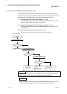
2: The ERR. LED of the following modules flashes if the module whose serial number (first five digits)
is "02112" or later is used.
• QJ72LP25-25
• QJ72BR15