


App - 15 App - 15
MELSEC-Q
APPENDICES
(3) List of link special register (SW) areas
The following lists the link special register (SW) areas (SW0000 to SW01FF).
POINT
(1) Do not turn ON the area which does not exist in the list.
Doing so may cause malfunction of the programmable controller system.
(2) For how to use the link special register (SW), refer to Section 6.6.
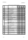
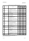
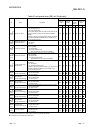
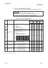
Table 3 Link special register (SW) list
No. Name Description
Availability
Control
station
Normal
station
Remote
master
station
Remote I/O
station
Optical Coaxial Optical Coaxial Optical Coaxial Optical Coaxial
1
SW0000
(0)
Link stop/startup direction
content
Sets the station that stops/restarts data linking.
00
H: Host
01
H: All stations
02
H: Designated station
80
H: Host (forced stop/restart)
81
H: All stations (forced stop /restart)
82
H: Designated station (forced stop /restart)
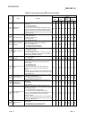
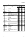
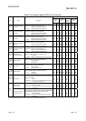
1
SW0001
(1)/
SW0002
(2)/
SW0003
(3)/
SW0004
(4)
Sets whether the designated station should execute data linking.
(When the SW0000 is 02
H or 82H.)
Sets the bits to 1 for stations whose data linking is
stopped/restarted.
0: Invalid data linking stop/restart instruction
1: Valid data linking stop/restart instruction
16
32
48
64
15 14 13 5 4 3 2 1
31 30
47 46
63 62
29
45
61
21 20 19 18 17
37 36 35
34
33
53 52 51 50 49
to
to
to
to
b15 b14 b13 b12 b4 b3 b2 b1 b0
SW0001
SW0002
SW0003
SW0004
The numbers 1 to 64 in the above table
indicate the station numbers.
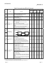
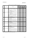
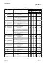
to
SW0008
(8)
Logical channel setting
(channel 1)
Sets the logical channel number for physical channel number 1.
(Valid only for channels on the receiving side)
0 : Logical channel number 1 (default)
1 to 64 : Other logical channel number is set.
SW0009
(9)
Logical channel setting
(channel 2)
Sets the logical channel number for physical channel number 2.
(Valid only for channels on the receiving side)
0 : Logical channel number 2 (default)
1 to 64 : Other logical channel number is set.
SW000A
(10)
Logical channel setting
(channel 3)
Sets the logical channel number for physical channel number 3.
(Valid only for channels on the receiving side)
0 : Logical channel number 3 (default)
1 to 64 : Other logical channel number is set.
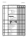
[Availability column] Optical: optical loop, Coaxial: coaxial bus
: Available, : Not available
1: Used in the network test of GX Developer.