


App - 35 App - 35
MELSEC-Q
APPENDICES
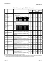
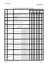
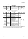
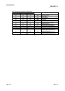
(3) Scan information
Special Relay List
Number Name Meaning Explanation
Set by
(When Set)
Corresponding
ACPU
M9
Corresponding
CPU
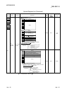
SM551
Reads module
service interval
OFF : Ignored
ON : Read
• When this relay is turned on, the service interval of the
module specified by SD550 is read to SD551 and
SD552.
U New
QnA
Qn(H)
QnPH
QnPRH
Rem
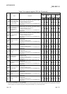
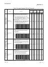
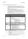
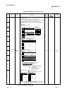
(4) Redundant power supply module information
Special Relay List
Number Name Meaning Explanation
Set by
(When Set)
Corresponding
ACPU
M9
Corresponding
CPU
SM
1780
Power supply off
detection flag
OFF : No redundant
power supply
module with input
power OFF
detected
ON : Redundant power
supply module with
input power OFF
detected
• Turns on when one or more redundant power supply
modules with input power off are detected.
• Turns on if any of SD1780 bits is on.
• Turns off if all bits of SD1780 are off.
• This relay turns off when the main base unit is not a
redundant main base unit (Q3
RB).
• When the multiple CPU system is configured, the flags
are stored only to the CPU No.1.
S
(Each END)
New
Qn(H)
*2
QnPH
*2
QnPRH
Rem
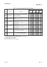
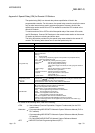
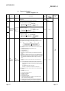
SM
1781
Power supply
failure detection
flag
OFF : No faulty
redundant power
supply module
detected
ON : Faulty redundant
power supply
module detected
• Turns on when one or more faulty redundant power
supply modules are detected.
• Turns on if any of SD1781 bits is on.
• Turns off if all bits of SD1781 are off.
• This relay turns off when the main base unit is not a
redundant main base unit (Q3
RB).
• When the multiple CPU system is configured, the flags
are stored only to the CPU No.1.
S
(Each END)
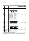
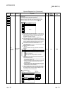
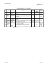
SM
1782
Momentary
power failure
detection flag for
power supply 1
*1 OFF : No momentary
power failure
detected
ON : Momentary power
failure detected
• Turns on when a momentary power failure of the input
power supply to the power supply 1 or 2 is detected one
or more times. After turning on, this relay remains on
even if the power supply recovers from the momentary
power failure.
• Turns off the flags (SM1782 and SM1783) of the power
supply 1 and 2 when the CPU module starts.
• When the input power to one of the redundant power
supply modules turns off, the corresponding flag turns off.
• This relay turns off when the main base unit is not a
redundant main base unit (Q3 RB).
• When the multiple CPU system is configured, the flags
are stored only to the CPU No.1.
S
(Each END)
SM
1783
Momentary
power failure
detection flag for
power supply 2
*1
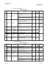
*1: The "power supply 1" indicates the redundant power supply module mounted on the POWER 1 slot of the redundant base unit (Q3 RB/Q6 RB/Q6 WRB).
The "power supply 2" indicates the redundant power supply module mounted on the POWER 2 slot of the redundant base unit (Q3
RB/Q6 RB/Q6 WRB).
*2: This applies to modules with a serial number (first five digits) of "07032" or later.
In multiple CPU systems, all CPU modules used in a system must be the ones with a serial number (first five digits) of "07032" or later.