


2 - 1 2 - 1
MELSEC-Q
2 SYSTEM CONFIGURATION
2 SYSTEM CONFIGURATION
This introduces a system comprised of remote I/O networks.
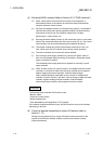
POINT
(1) Remote I/O networks and PLC to PLC networks cannot be mixed on the same
MELSECNET/H network. Always build separate networks.
(2) Only MELSECNET/H network modules can be connected to a MELSECNET/H
remote I/O network. They cannot be mixed with MELSECNET/10 network
modules (AJ72LP25, A1SJ72QLP25, etc.).
2.1 Single Remote I/O Networks
2.1.1 Configuration
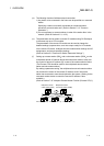
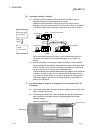
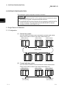
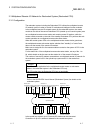
(1) Optical loop system
Up to 64 remote I/O modules can be connected to a remote master station.
Always set the station number of the remote master station to 0.
Power supply
QCPU QJ71
LP21
Station number 0
(remote master station)
Station number 1
(remote I/O station)
I/O
QJ72
LP25
I/O
Station number 2
(remote I/O station)
I/O
QJ72
LP25
I/O
Optical fiber cable
Power supply
Power supply
I/O
QJ72
LP25
I/O I/O
QJ72
LP25
I/O
Power supply
Power supply
I/O
QJ72
LP25
I/O
Power supply
Station number 4
(remote I/O station)
Station number 3
(remote I/O station)
Station number 64
(remote I/O station)
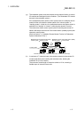
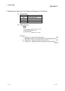
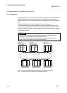
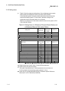
(2) Coaxial cable bus system
Up to 32 remote I/O stations can be connected to a remote master station.
Always set the station number of the remote master station to 0.
QCPU
QJ71
BR11
Terminating resistor
(Sold separately)
Terminating resisto
r
(Sold separately)
Coaxial cable
Station number 1
(remote I/O station)
I/O
QJ72
BR15
I/O
Station number 32
(remote I/O station)
I/O
QJ72
BR15
I/O
Power supply
Power supply
Power supply
Station number 0
(remote master station)
2