


8 - 21 8 - 21
MELSEC-Q
8 TROUBLESHOOTING
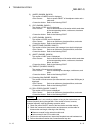
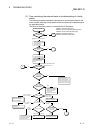
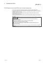
8.2.1 Items checked first
Check item Checking procedure
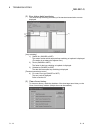
Monitor the transmission status of each station
with GX Developer 's network diagnostics.
Check the CPU module status of the faulty station, the status of the network modules,
the loop status of each station to search for the location where the error has occurred.
Is the "ERR." LED of the CPU module still lit or
flickering?
Read the error code using GX Developer, and take proper measures against the error.
(For details, refer to the QCPU User's Manual (Hardware Design, Maintenance and
Inspection).
Check the following when LINK PARA. ERROR occurs.
1) Check whether the starting I/O No. in the network setting matches the slot where the
network module is installed. (Refer to Section 5.1.2.)
2) Check for consistency in the network type and the station number of the network
module. (Refer to Section 5.1.1.)
3) Check if the PLC side device ranges in Refresh parameters are within the ranges set
in [PLC parameter] - [Device]. (Refer to Section 5.1.5 (2).)
If refresh parameters have not been set, set them according to the changes made in
[Device] under [PLC parameter]. (Refer to Section 5.1.5 (3).)
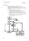
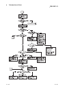
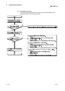
Are the LEDs of the remote I/O station operating
normally?
Check the "RUN", "ERR", and "L ERR" LEDs and take the corrective action if any error
is found. (Refer to Section 4.2.)
Are the “RUN,” “REM.,” “T.PASS,” and “D.LINK”
LEDs of the remote I/O module on?
Are the “ERR.,” and “L ERR” LEDs off?
If the “RUN,” “REM.,” “T.PASS,” and “D.LINK” LEDs are OFF or the “ERR.” and “L
ERR.” LEDs are ON, diagnose the remote I/O module by GX Developer.
(Refer to Section 4.2.)
If the status of the "T. PASS" or "L ERR." LED is unstable, refer to the following.
<Cause>
The line status may be unstable.
<Troubleshooting>
1) Check the connector for loose connection and the cable for a break.
2) Check that the cable used conforms to the specifications.
3) Check that the overall length and interstation distance conform to the specifications.
(Refer to Section 4.8 Cable Connection.)
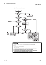
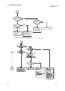
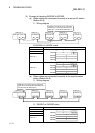
Are the "RUN" and "REM." LEDs on the remote
I/O module on?
If the LEDs are out, use GX Developer to diagnose the remote I/O module.
Has the error reset process using SM50/SD50
been performed after the online module change
function was executed on a remote I/O station?
Perform the error reset process by the procedure below after executing the online
module change function.
1) Perform the error reset process on the remote I/O station.
2) Perform the error reset process on the programmable controller CPU of the master
station.
Are the ERR contacts of the power supply
modules of the remote master station and remote
I/O station on?
1) If the ERR contact of the power supply module of the remote master station is OFF,
check the status of the power supply connected to the power supply module of the
remote master station, or diagnose by GX Developer if a stop error has not occurred
on the CPU module of the remote master station.
2) If the ERR contact of the power supply module of a remote I/O station is OFF, check
the status of the power supply connected to the power supply module of the remote
I/O station, or diagnose by GX Developer if a stop error has not occurred on the
remote I/O module of the remote I/O station. However, the ERR contact of the power
supply module of the remote I/O station is turned off instantaneously when
parameters are received from the remote master station after the parameters of the
remote I/O station are changed. (The ERR contact is turned on when communication
becomes ready due to the reception of parameters.)
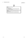
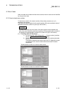
8.2.2 Items checked when data link cannot be performed throughout the system
Check item Checking procedure
Monitor the communication status of each station
with GX Developer's network diagnostics.
Check the line condition with GX Developer's network diagnostic loop test (only in case
of optical loop test).
Check the faulty station's CPU module and network module.
Check the network module and data link cable with the self-loopback test and station-
to-station test of the offline tests.
Check whether data linking is stopped for all stations.
Are the network parameters set for the remote
master station?
Check whether the network parameters from the remote master station's CPU module
are set.
Are the switch settings of the remote master
station's master module correct?
Check the station number setting switches and mode setting switch.
Are the switches of the network modules on all
stations set in the correct position?
Make sure that the mode setting switches of the network modules on all stations are in
the same position.
Is the link monitoring time set to a sufficient value?
Set the link monitoring time to the maximum value and check whether or not data
linking can be performed.
Did the remote master station go down? Check the on/off status of the LEDs of the master modules of the remote master station.