


App - 48 App - 48
MELSEC-Q
APPENDICES
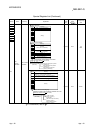
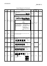
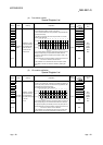
(4) Fuse blown module
Special Register List
Number Name Meaning Explanation
Set by
(When set)
Corresponding
ACPU
D9
Corresponding
CPU
SD1300
Fuse blown
module
Bit pattern in units of
16 points, indicating
the modules whose
fuses have blown
0: No blown fuse
1: Blown fuse
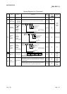
• The number of an output module whose fuse has blown is stored
in the following bit pattern (in units of 16 points).
(If the module numbers are set by parameter, the parameter-set
numbers are stored.)
• The status of the blown fuse of an output module on a remote
station is also detected.
1514131211109876543210
0
0
0
1
(YC0)
000 00000000
1
(Y80)
SD1300
00
1
(Y1F0)
0 0 00000000
1
(Y1A)
SD1301
00
00
1
(Y1F
B0)
00000000
SD1331
000
1
(Y1F
30)
0
Indicates a blown fuse
• For a module whose number of output points exceeds 16 points,
all bits corresponding to output module numbers within the
number of output points occupied by the module (in units of 16
points) turn on.
(Example) When a 64-point module is mounted on the slot 0, b0
to b3 turn on when the fuse has blown.
• The module No. is not cleared even when the output module
goes back to normal. The number is cleared by clearing the
error.
S (Error)
D9100
QnA
Qn(H)
QnPH
QnPRH
QnU
Rem
SD1301 D9101
SD1302 D9102
SD1303 D9103
SD1304 D9104
SD1305 D9105
SD1306 D9106
SD1307 D9107
SD1308 New
SD1309
to
SD1330
New
SD1331 New
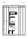
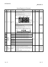
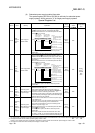
(5) I/O module verification
Special Register List
Number Name Meaning Explanation
Set by
(When set)
Corresponding
ACPU
D9
Corresponding
CPU
SD1400
I/O module
verify error
Bit pattern, in units of
16 points, indicating
the module with an
I/O module verify error
0: No error
1: Error
• If the status of the I/O module changes from that obtained at
power-on, the module No. is stored in the following bit pattern (in
units of 16 points). (If the I/O numbers are set by parameter, the
parameter-set numbers are stored.)
• I/O module information is also detected.
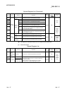
15
14
13
12 11
10 9 8
7
65
4
3
21
0
000 000 0000000
SD1400
00 0 00000000
SD1401
00
0 0 0000 000
SD1431
0000
00
00
00
1
( )
X Y
1FE0
1
( )
1
( )
X Y
190
X Y
0
Indicates an I/O module verification erro
r
• For a module whose number of I/O points exceeds 16 points, all
bits corresponding to I/O module numbers within the number of
I/O points occupied by the module (in units of 16 points) turn on.
(Example) When a 64-point module is mounted on the slot 0, b0
to b3 turn on when an error is detected.
• The module No. is not cleared even when the I/O module goes
back to normal. The number is cleared by clearing the error.
S (Error)
D9116
QnA
Qn(H)
QnPH
QnPRH
QnU
Rem
SD1401 D9117
SD1402 D9118
SD1403 D9119
SD1404 D9120
SD1405 D9121
SD1406 D9122
SD1407 D9123
SD1408 New
SD1409
to
SD1430
New
SD1431 New