


3 - 2 3 - 2
MELSEC-Q
3 SPECIFICATIONS
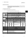
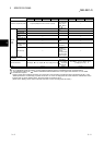
Item
Remote master station Remote I/O station
QJ71LP21 QJ71LP21G QJ71LP21GE QJ71LP21-25 QJ71LP21S-25 QJ72LP25-25 QJ72LP25G QJ72LP25GE
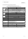
Number of occupied I/O points 32 points (Intelligent function module: 32 points)
48 points
(I/O Assignment:
empty; first 16,
intelli.; second
32)
4
—
External
Power
Supply
Voltage
—
20.4 to 31.2 V
DC
—
Current
—
0.20 A
—
Size of terminal
screw
—
M3 Screw
—
Suitable crimp
terminal
—
R1.25-3
—
Suitable cable size
—
0.3 to 1.25 mm
2
—
Tightening torque
—
0.42 to 0.58
N
m
—
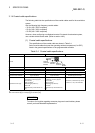
Allowable
momentary power
failure time
—
1ms
(Level PS1)
—
Noise immunity —
By noise
simulator of
500Vp-p noise
voltage,
1ms noise width,
and 25 to 60Hz
noise frequenc
y
—
5 V DC internal current
consumption
0.55 A 0.89 A
External dimensions
98 (3.86)(H)
27.4 (1.08)(W) 90 (3.54)(D) [mm (inch)]
98 (3.86)(H)
55.2 (2.18)(W)
90 (3.54)(D)
[mm(inch)]
98 (3.86)(H)
27.4 (1.08)(W) 90
(3.54)(D) [mm (inch)]
Weight 0.11 kg 0.20 kg 0.15 kg
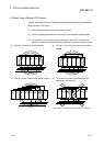
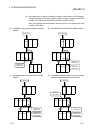
1: The remote master station includes the multiplexed remote master station and multiplexed remote sub-master station.
2: On a multiplexed remote I/O network, one of 64 remote I/O stations works as a multiplexed remote sub-master station.
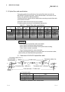
3: The optical fiber cable (A-2P-
) differs in interstation distance between the L and H types. Refer to Section 4.8.1 for details.
4: Two slots are occupied.
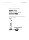
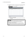
Set the numeric value resulted from adding 10
H to the I/O No. of the slot where a module mounted as the “Starting I/O No.” of the
“Network parameter”. The first empty 16 points can be set to “0” on the “I/O assignment” tab screen within the “Q Parameter” screen.
Example: Set 10
H as the “Starting I/O No.” when the module is mounted on slot 0.
(Set 0
H as the “Starting I/O No.” when 0 has been set to slot 0 on the “I/O assignment” tab screen.)
3