


7 - 32 7 - 32
MELSEC-Q
7 APPLICATION FUNCTIONS
7.11 Multiplexed remote master function for the redundant system (Redundant CPU)
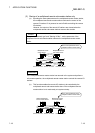
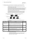
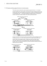
The redundant system uses the multiplexed remote master function to control I/O
modules and intelligent function modules.
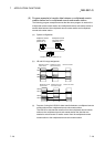
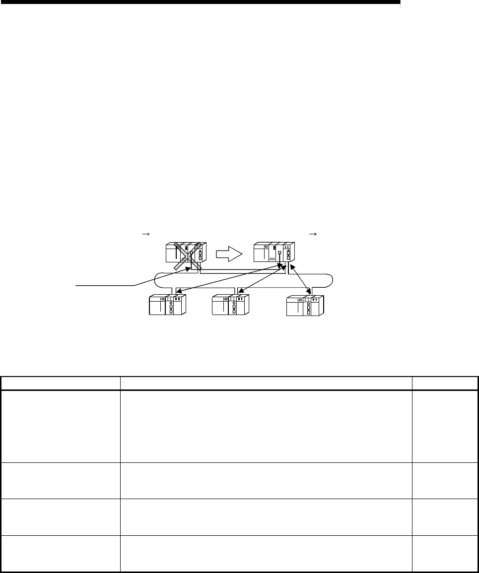
The multiplexed remote master function for the redundant system continues the control
of remote I/O stations when the multiplexed remote master station (control system)
fails by switching the multiplexed remote master station from the control system to the
standby system and switching the multiplexed remote sub-master station (standby
system) from the standby system to the control system.
The multiplexed remote sub-master station (control system) which is controlling a
remote I/O station continues the control of the remote I/O station even after the
multiplexed remote master station (standby system) returns to the normal status.
Multiplexed remote master station (DM
R
)
Control system Standby system
Multiplexed remote sub-master station (DSM
R
)
Standby system Control system
Remote I/O station (R)
Remote I/O station (R)
Remote I/O station (R)
Tracking cable
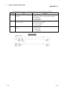
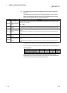
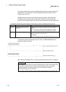
The multiplexed remote master function for the redundant system includes the
following features.
Item Description Reference section
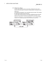
(1) Backup function of master
operation on system
switching between control
system and standby system
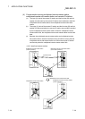
When a power supply error or CPU error occurs in the control system, the
Redundant CPU in the standby system continues the operation of the redundant
system by switching to the control system. With the system switching, the
multiplexed remote sub-master station switched from the standby system to the
control system takes over master operation to continue the control of remote I/O
stations.
Section 7.11.1
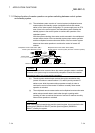
(2) Master operation by the
station that has started up as
the control system
The master module mounted with the Redundant CPU that has started up as the
control system operates as the master station. The master module mounted with the
CPU that has started up as the standby system operates as the sub-master station.
Section 7.11.2
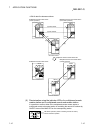
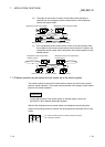
(3) System switching request
function of control system
The master module mounted in the control system CPU issues the system switching
request to the control system CPU when a data link error such as link cable
disconnection or transmission error are detected.
Section 7.11.3
(4) Access function by specifying
control system or standby
system
Access from GX Developer or others to Redundant CPU can be performed by
specifying the control system/standby system instead of station No. Therefore, the
control system can be accessed any time even if system is switched.
Section 7.11.4
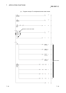
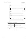
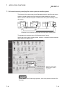
(1) Network parameter settings
It is not required to create each project for control system/standby system. In a
redundant system, parameters and sequence programs common to both
systems can be created in one project.