


4 - 10 4 - 10
MELSEC-Q
4 SETTING AND PROCEDURE BEFORE OPERATION
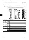
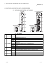
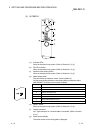
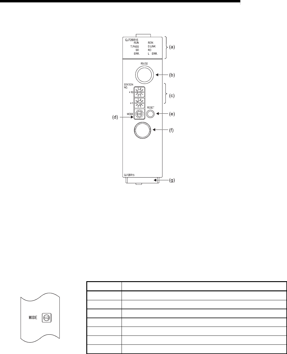
(2) QJ72BR15
(a) Indicator LEDs
Same as the optical loop system. (Refer to Section 4.2.2 (1).)
(b) RS-232 connector
Same as the optical loop system. (Refer to Section 4.2.2 (1).)
(c) Station number setting switch
Same as the optical loop system. (Refer to Section 4.2.2 (1).)
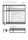
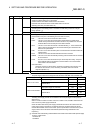
(d) Mode setting switch
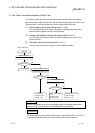
This switch sets the operation mode. (Factory default: 0)
Set the mode setting switches in the same position (except the online
(MELSECNET/10 mode)) on all network modules.
Setting Description
0 Online
1 Self-loopback test
2 Internal self-loopback test
3 Hardware test
4 to 7 Use prohibited
8 Online (MELSECNET/10 mode)
9 to F Use prohibited
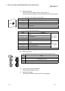
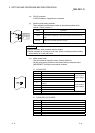
(e) RESET switch
Same as the optical loop system. (Refer to Section 4.2.2 (1).)
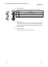
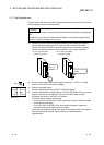
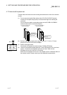
(f) Coaxial connector
An F-type connector for a coaxial cable is connected. (Refer to Section
4.8.2.)
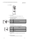
(g) Serial number display
The serial number on the rating plate is displayed.