


App - 38 App - 38
MELSEC-Q
APPENDICES
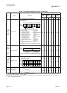
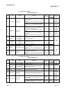
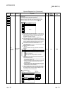
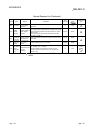
Special Register List (Continued)
Number Name Meaning Explanation
Set by
(When
set)
Corresponding
ACPU
D9
Corresponding
CPU
SD5
Error
common
information
Error common
information
• This register stores common information corresponding to the error code
stored in SD0.
• The following five types of information are stored here.
• The error common information type can be determined by "common
information category code" stored in SD4. (Values stored in "common
information category code" correspond to the following
1
to
5
.)
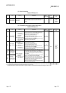
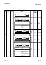
1
Module No.
SD5
SD6
SD7
SD8
SD9
SD10
SD11
SD12
SD13
SD14
SD15
Meaning
(Empty)
Number
Slot No./CPU No. 1 2 3 4
I/O No. 5
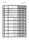
1: For the multiple CPU system using the Basic model QCPU, High
Performance model QCPU, Process CPU, and Universal model
QCPU, the slot No. or CPU No. is stored according to an error.
(For details, refer to each error code.)
CPU No.1: 1, CPU No.2: 2, CPU No.3: 3, CPU No.4: 4
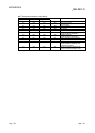
2: If a fuse has been blown or an I/O module verify error occurs in a
module on the MELSECNET/H remote I/O station, the network No.
is stored in the upper 8 bits and the station No. is stored in the lower
8 bits. To determine a fuse-blown module or a module where an
I/O module verify error occurs, check the I/O No.
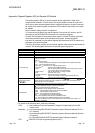
3: If an instruction is executed from the Basic model QCPU to a
module mounted on the slot where no module should be mounted,
"255" is stored in SD5.
4: Definitions of base No. and slot No.
<Base No.>
This number indicates a base unit on which the CPU module is
mounted.
Base No.
0
1 to 7
Definition
Indicates the main base unit mounted with the CPU module.
Indicates the extension base unit. The stage number setting
made by the stage number setting connector on the extension
base unit is the base No.
When stage number setting is extension 1: Base No. = 1
when stage number setting is extension 7: Base No. = 7
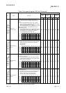
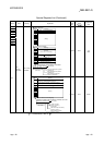
<Slot No.>
This number is used to identify the slot of each base unit and a
module mounted on the slot.
• The "0" I/O slot (slot on the right of the CPU slot) on the main base
unit is defined as "Slot No. = 0".
• The slot Nos. are assigned in sequence numbers in order of the
main base unit and then the first extension base unit to 7th
extension base unit.
• When the number of slots on base units has been set in the I/O
assignment tab of the PLC Parameter dialog box, the slot Nos.
are assigned by the number of set slots.
5: If FFFFH is stored in SD6 (I/O No.), this indicates that the I/O No.
cannot be identified due to an error such as overlap of an I/O No. in
the I/O assignment tab of the PLC Parameter dialog box. In this
case, identify the error location using SD5.
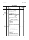
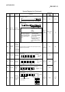
2 File name/Drive name
Number
SD5
SD6
SD7
SD8
SD9
SD10
SD11
SD12
SD13
SD14
SD15
Meaning
Drive
2E
H
(.)
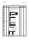
File name
(ASCII code: 8 characters)
(Empty)
42H(B) 41H(A)
44
H(D) 43
H
(C)
46
H(F) 45H(E)
48
H
(H) 47
H
(G)
49
H
(I) 2E
H
(.)
4B
H
(K) 4A
H
(J)
B15 to B8 B7 to B0
(Example)
File name=
ABCDEFGH. IJK
Extension
(ASCII code: 3 characters)
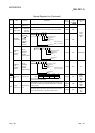
6
S (Error) New
Rem
SD6
SD7
SD8
SD9
SD10
SD11
SD12
SD13
SD14
SD15