


4 - 25 4 - 25
MELSEC-Q
4 SETTING AND PROCEDURE BEFORE OPERATION
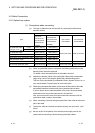
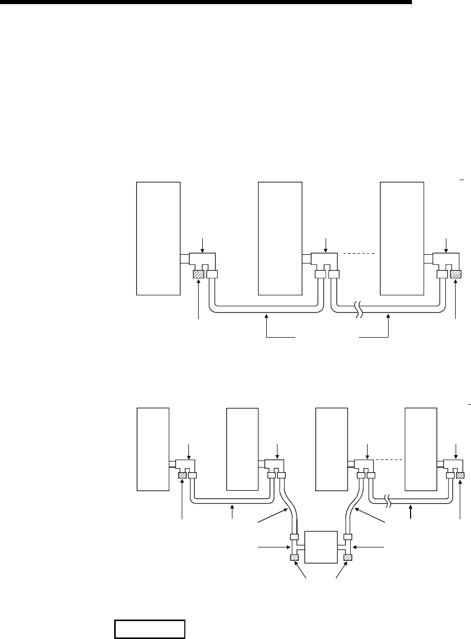
(2) Cable connection
(a) Connection method
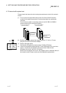
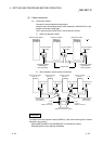
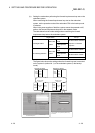
Connect the coaxial cable as shown below.
Always install a terminating resistor (sold separately: A6RCON-R75) to the
stations connected at both ends.
The F-type connector (A6RCON-F) comes with the module.
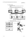
1) Without a repeater module
QJ71BR11 QJ72BR15
Remote master station
Station No. 0
Remote I/O station
Station No. n
Remote I/O station
Station No. 1
F-type connector
A6RCON-F
Coaxial cable
Terminating resistor
A6RCON-R75
(
sold se
p
aratel
y)
F-type connector
A6RCON-F
F-type connector
A6RCON-F
Terminating resistor
A6RCON-R75
(
sold se
p
aratel
y)
n
32
QJ72BR15
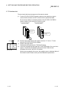
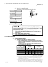
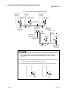
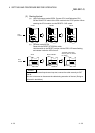
2) With a repeater module (series connection)
A6BR10
QJ71BR11
Remote master station
Station No. 0
Remote I/O station
Station No. 1
Remote I/O station
Station No. 2
QJ72BR15
Remote I/O station
Station No. n
F-type connector
A6RCON-F
Coaxial cable
T-type
connector
(A6BR10 accessory)
T-type
connector
(A6BR10 accessory)
Coaxial cable
Terminating resistor
A6RCON-R75
(sold separately)
Terminating resistor
A6RCON-R75 (sold separately)
F-type connector
A6RCON-F
F-type connector
A6RCON-F
F-type connector
A6RCON-F
Terminating resistor
A6RCON-R75
(sold separately)
n
32
QJ72BR15QJ72BR15
REMARKS
For details about the repeater module (A6BR10), refer to the following user's manual
attached to the product:
Model A6BR10/A6BR10-DC MELSECNET/10 Coaxial Bus System
Repeater Module User's Manual (IB-66499)