


4 - 26 4 - 26
MELSEC-Q
4 SETTING AND PROCEDURE BEFORE OPERATION
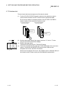
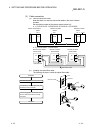
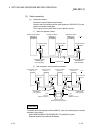
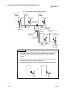
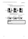
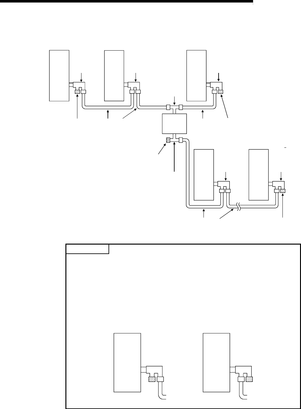
3) With a repeater module (branch connection)
QJ71BR11 QJ72BR15
QJ72BR15
F-type connector
A6RCON-F
Coaxial cable
A6BR10
T-type connector
(A6BR10 accessory)
T-type connector
(A6BR10 accessory)
Terminating resistor
A6RCON-R75
(sold separately)
Remote master station
Station No. 0
Remote I/O station
Station No. 1
Remote I/O station
Station No. 2
F-type connector
A6RCON-F
F-type connector
A6RCON-F
Coaxial cable
Terminating resistor
A6RCON-R75
(sold separately)
Terminating resistor
A6RCON-R75
(sold separately)
F-type connector
A6RCON-F
F-type connector
A6RCON-F
Remote I/O
station
Station No. 3
Remote I/O station
Station No. n
Coaxial cable
Terminating resistor
A6RCON-R75
(sold separately)
n
32
QJ72BR15
QJ72BR15
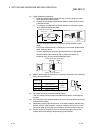
POINT
(1) By setting stations that will be connected in future (stations that are included in
the number of stations but not actually connected) as reserved stations, a
communication error can be prevented and the link scan time will not be
affected.
(2) The two connectors of the F-type connector are not dedicated to IN and OUT.
A coaxial cable can be connected to either of them.
(3) A terminating resistor can be placed on either side of the F-type connector.
or