


4 - 19 4 - 19
MELSEC-Q
4 SETTING AND PROCEDURE BEFORE OPERATION
4.7.3 Hardware test
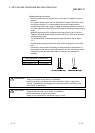
This test checks the internal components of the network module.
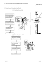
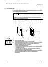
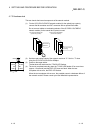
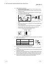
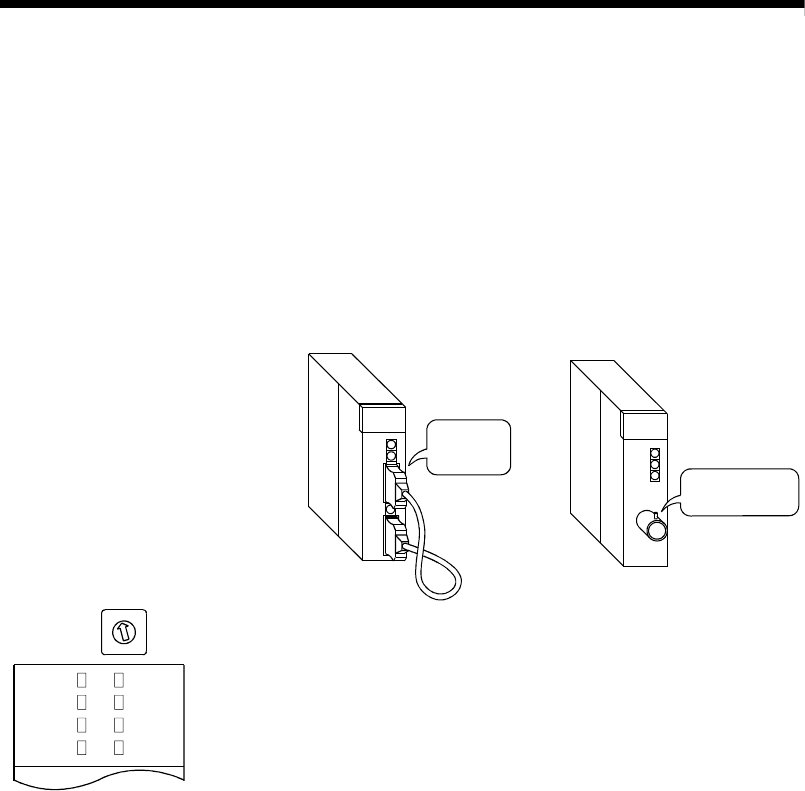
(1) For the QJ71LP21/QJ72LP25 network module (for the optical loop system),
connect the IN connector and OUT connector with an optical fiber cable.
Do not connect cables or terminating resistors if the QJ71BR11/ QJ72BR15
network module (for the coaxial bus system) is used.
IN
OUT
For QJ71LP21/QJ72LP25
(optical loop system)
For QJ71LP21/QJ72BR15
(coaxial bus system)
Connect IN
and OUT
Do not connect
anything
MODE
3
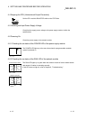
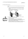
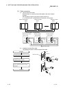
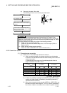
(2) Set the mode setting switch of the network module to "3". Set it to "7" when
using the QJ71LP21/QJ72LP25 at 25Mbps.
RUN
MNG
T.PASS D.LINK
SD
RD
ERR. L ERR.
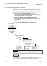
(3) Power on the target station.
The hardware test starts and the T.PASS LED flashes.
(4) The test is completed normally when the T.PASS LED flashes 20 or more times
(approx. 10 seconds) and the ERR. LED does not flash. When the test
completes with an error, the ERR. LED flashes.
When the test completes with an error, the possible cause is a hardware failure of
the network module. Please consult your local Mitsubishi representative.